Author: icextractor

  • TMS320F28026 Readout: 32 KB Flash On A 48-Pin Piccolo

    TMS320F28026 Readout: 32 KB Flash On A 48-Pin Piccolo

    The TMS320F28026 is the smallest Piccolo that ships with a full code security module, and that decides how a readout is planned. It carries 16,384 words of flash — 32 KB — alongside 6,144 words of single-access RAM, 1K word of OTP and an 8K word boot ROM, all driven by a 60 MHz C28x core with a 16.67 ns cycle. Twenty-two GPIO pins, one SCI, one SPI and one I2C are what the package exposes on the 48-pin PT LQFP; the 38-pin DA TSSOP gives up ten of those pins and six of the thirteen ADC inputs.

    Readout Texas Instrument TMS320F28026 Processor Memory Program starts from attack tms320f28026 dsp mcu's protective system and then clone the software data to new microcontroller tms320f28026;
    Readout Texas Instrument TMS320F28026 Processor Memory Program starts from attack tms320f28026 dsp mcu’s protective system and then clone the software data to new microcontroller tms320f28026;

    What The Array Looks Like Before Anything Is Read

    A 32 KB array is small enough to hold in a single pass, which changes the economics of the job. There is no need to segment the read into sessions or to checkpoint halfway; the whole program fits in one contiguous window that starts at 0x3E8000 and ends at the top of the map. What does not change is the tail of that window. The last eight words — 0x3F7FF8 through 0x3F7FFF — hold the 128-bit code security password, and they are the reason a naive dump returns a valid-looking image that will not run anywhere.

    Those eight words are not a checksum and they are not a magic number. They are compared, word for word, against whatever the debugger or the CPU writes into the CSM key registers. A single mismatched word leaves the module locked, and a locked module returns zeros for every fetch inside the protected range while happily serving the boot ROM and the peripherals. The failure looks like a dead part rather than a protected one, which is where most first attempts stall.

    Why The Password Is Usually Recoverable

    Three things routinely give the password away on this device. The first is a production batch: parts programmed from the same project file usually share a password, so a single unlocked sample from the same lot authenticates the rest. The second is the OTP row. Engineers sometimes burn a build identifier or a serial there and, less often, a copy of the key. The third is the boot loader path — if the part was ever reflashed in the field over SCI, the flashing tool’s log or the image header may still carry the value.

    When none of those exist, the password is not guessed. Brute force against 128 bits is not a plan; the array is read directly instead.

    Reading Without The Key

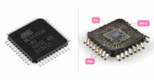
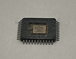
    Direct readout means opening the package and reaching the flash macro itself. The mould compound comes off, the passivation is etched back, and a probe lands on the sense amplifier outputs or the column lines depending on how the array is laid out. The F28026 die is small, so the array is reachable without thinning the whole surface, and the read is done at low enough voltage that the cells are not disturbed.

    The array is read as raw words, before ECC and before any address scrambling the boot ROM applies; the descrambling has to be reconstructed from the known-good region, which is why an erased or partially erased part is harder than a full one. Second, erased words read as 0xFFFF, and a protected region that was never programmed is indistinguishable from one that was deliberately blanked. We mark those regions explicitly rather than letting them look like code.

    TMS320F28026 code security module readout
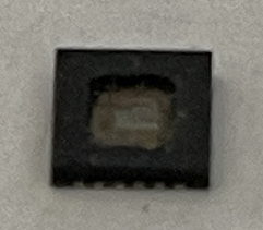
    Texas Instruments TMS320F28026 Piccolo microcontroller

    Rebuilding Something That Boots

    The output of a raw read is not a firmware image yet. It becomes one after the vector table is checked against the reset entry, the code starts are located, and the checksum of each contiguous block is compared with what the linker would have produced. On a 32 KB part this is quick, but a single transposed word in the PIE vector table still boots and then fails the first interrupt.

    We test that by loading the rebuilt image into a blank F28026 and running it against the original board’s behaviour — PWM start-up sequence, ADC trigger timing, SCI baud rate at the crystal the customer uses. A rebuilt image that passes those three is the program.

    What Leaves The Bench

    The delivery for this part is an Intel HEX covering the full 32 KB, a binary of the same, the recovered password if one was found, a sector map showing which regions were programmed, and the checksum table. If you have a batch of F28026 units that will not yield to a programmer, the readout service covers the decapsulation and the array read, and the contact form is the fastest way to get a quote with your quantity and package. For the 64 KB sibling, the TMS320F28027 route uses the same bench setup; the 32 KB F28030 with the larger pin count is covered under the TMS320F28030 job.

  • STM32F105VCT Microprocessor Flash Memory Binary Replicating

    STM32F105VCT Microprocessor Flash Memory Binary Replicating

    STM32F105VCT Microprocessor Flash Memory Binary Replicating will require to decrypt secured memory program file from arm microcontroller stm32f105vct after unlock fuse bit of stm32f105vct arm mcu;

    The electromagnetic field emitted by the device are monitored while a simple application is executed to facilitate the progress of copy stm32f105rct arm microprocessor flash binary (toggling 2 LEDs through the I/O ports). This emission test is compliant with SAE IEC61967-2 standard which specifies the test board and the pin loading.

    STM32F105VCT memory read-out after fuse unlock
    STM32F105VCT ARM microcontroller on the target board

    Based on three different tests (ESD, LU) using specific measurement methods, the device is stressed in order to determine its performance in terms of electrical sensitivity.

    STM32F105VCT Microprocessor Flash Memory Binary Replicating will require to decrypt secured memory program file from arm microcontroller stm32f105vct after unlock fuse bit of stm32f105vct arm mcu
    STM32F105VCT Microprocessor Flash Memory Binary Replicating will require to decrypt secured memory program file from arm microcontroller stm32f105vct after unlock fuse bit of stm32f105vct arm mcu

    Electrostatic discharges (a positive then a negative pulse separated by 1 second) are applied to the pins of each sample according to each pin combination in order to restoring arm microcontroller stm32f103 flash binary. The sample size depends on the number of supply pins in the device (3 parts × (n+1) supply pins). This test conforms to the JESD22-A114/C101 standard.

    STM32F105VCT ARM microcontroller on the target board
    Decrypting the STM32F105VCT secured flash binary

    Static latch-up

    Two complementary static tests are required on six parts to assess the latch-up performance:

    • A supply overvoltage is applied to each power supply pin
      • A current injection is applied to each input, output and configurable I/O pin These tests are compliant with EIA/JESD 78A IC latch-up standard.
  • Copy Microcontroller Program

    Copy Microcontroller Program

    Copying a microcontroller program means reading the code that already lives inside a chip and turning it back into a file you can archive, compare, or load into another unit. On an unlocked part that is a five-minute job for any programmer. On a production part with code read protection enabled, the same request returns nothing but zeros, and the question becomes a hardware one: how do you get the die to give up its contents when the silicon is built to refuse.

    Why A Protected MCU Returns Nothing

    Read protection is not one mechanism but a family of them, and each vendor implements it differently. NXP LPC parts use Code Read Protection levels that close the debug port and restrict ISP entry once CRP1 or higher is set. STM32 parts use readout protection at level 1 or 2, where level 2 closes the debug interface permanently. AVR parts use lock bits that disable both the debugWIRE interface and program memory verification. Older 8051 and PIC families gate access behind a security fuse.

    The common outcome is the same. The debug port refuses to connect, a memory read comes back as a uniform pattern of zeros or 0xFF, and the bootloader rejects any attempt to verify the flash contents. Nothing is necessarily broken; the part is simply answering every question with a refusal.

    What The Copy Has To Contain

    A usable copy is more than a blob of code. Three things usually have to come out together, and skipping any of them produces a file that will not reproduce the original behaviour:

    • Program flash — the actual machine code, including any bootloader region that sits above the application.
    • Data EEPROM — calibration constants, serial numbers, run-hour counters and keys that the firmware expects to find at fixed addresses.
    • Option or configuration bytes — brown-out thresholds, watchdog settings, clock source selection and the protection state itself.

    A dump that captures only the flash leaves the receiver with a program that boots into a fault because its calibration table is empty. This is the single most common reason a copied file fails on a new board.

    How The Program Is Actually Pulled Out

    There is no universal trick. The route depends on the part, its package, and exactly which protection level is active. In practice a read-out follows one of four paths, chosen after the device has been inspected:

    • Debug or bootloader entry — when protection is partial or a vendor-specific backdoor sequence exists, the memory can be read through the intended interface without touching the package.
    • Decapsulation and direct readout — the epoxy or ceramic lid is removed to expose the die, and the flash array is read optically or with a microprobe. This is the path of last resort and the most expensive.
    • Fault injection — a precisely timed voltage or clock glitch forces the part past its protection check during boot, after which the flash can be read normally.
    • Side-channel analysis — power consumption or electromagnetic emission is measured while the chip runs and correlated against known operations to recover internal state.

    On a well-protected modern part, one route rarely suffices. A typical job combines a non-invasive attempt first, then a decapsulation step if the fuse holds, then a repair pass if the die was damaged in the process.

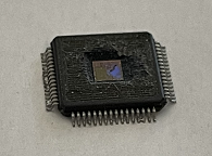
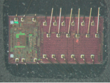
    Microcontroller die exposed after the package has been decapsulated for direct flash readout

    Flash And EEPROM Are Two Separate Jobs

    Flash and data EEPROM sit in different arrays and are often protected independently. Flash is organised in pages or sectors and is usually read as a whole image, because a partial read leaves the vector table pointing at gaps. EEPROM is typically a small array holding the values the program needs at run time — the part-specific calibration that makes one unit behave differently from the next.

    On some parts the EEPROM survives a mass erase that wipes the flash, and on others it is cleared at the same moment. Whether you need the EEPROM recovered has a direct effect on the method and the price, so it is worth deciding before the job starts rather than after.

    What The Delivered File Looks Like

    The output is normally an Intel HEX image with the original addresses preserved, alongside a raw binary for tools that expect one. Both are accompanied by a checksum and a short memory map showing which regions were read, which were empty, and which could not be reached. Where a region is unreadable — a protected boot sector or a one-time-programmable area — the report says so explicitly instead of filling the gap with zeros.

    Correctness is checked by reading the device twice through independent paths and comparing the two images byte for byte. If the two reads disagree, the job is not finished.

    Time And Cost Are Driven By Four Things

    Two parts with the same part number can take very different amounts of work, because the variables that matter are physical rather than electrical:

    • Package — a QFP or SOP can often be handled without decapsulation, while a BGA or chip-on-board assembly needs more preparation before the die is even reachable.
    • Protection level — a level-1 part may open through a glitch in an afternoon, while a level-2 part with an active shield can take weeks.
    • Die condition — a part that has already been attacked, over-etched, or damaged during removal costs more to recover.
    • Quantity — the first unit carries the entire setup cost; additional units of the same type are far cheaper once the path is known.

    What We Ask For Before Starting

    A read-out request moves faster when it arrives with the details that determine the route. We ask for the full part number including any suffix, a clear photograph of the package marking, the board it came from if the part is soldered down, and a statement that you own the design or hold the rights to the firmware. Work is only accepted on that basis.

    Frequently Asked Questions

    Can a program be copied from a chip with read protection enabled? Yes, in most cases, but through hardware work rather than a programmer. The protection blocks software access, not physical readout.

    Does the chip survive the process? Non-invasive routes leave the part working. Decapsulation is destructive by nature — the package is opened — and the die may not be reusable afterwards, though the extracted data is unaffected.

    Do I receive source code? No. What comes back is the compiled machine code and the data arrays. Recovering readable source from a binary is a separate reverse-engineering exercise and is not part of a read-out.

    How do I know the copy is correct? Every delivery includes a checksum and a memory map, and the image is verified by two independent reads before it is released.

    Can you handle a single unit? Yes. Single-unit work is the normal case; volume only becomes relevant when the same part type repeats.

    Related Reading

    If the part in question is a Microchip 32-bit device, the PIC32MX extraction index lists every device in that branch with its flash geometry. For the wider process see extracting MCU embedded firmware, and for the physical side of the work see MCU extraction. To start a job, send the part details through the contact form or review the services we offer.

  • Extract IC Code

    Extract IC Code

    Extract IC Code methods can be divided into three different kinds, they are include invasive MCU Crack method, invasive Microcontroller Unlocking need to reverse engineering to analyze the internal structure, and extract the netlist and schematic;

    Extracting IC (Integrated Circuit) code involves retrieving firmware, data, or source code from microcontroller units (MCUs), EEPROMs, flash memory, and other embedded systems. Engineers and security researchers often perform this task for reverse engineering, firmware recovery, or cloning purposes. The process may include cracking protection mechanisms, decrypting secured data, or decoding raw binary files.

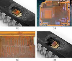
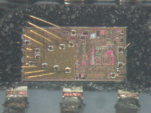
    Invasive decapsulation of an integrated circuit
    Invasive decapsulation of an integrated circuit

    Common Methods for IC Code Extraction
    Dumping Memory Contents

    The most straightforward method is to dump the contents of flash memory or EEPROM into a binary or hexadecimal file. Tools like logic analyzers, flash programmers, or specialized hardware (e.g., CH341A programmer) can extract firmware directly from the IC.

    Some chips have readout protection, requiring attackers to bypass security measures before obtaining a full memory dump.

    Decapsulating and Microprobing

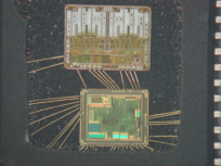
    IC flash memory die under microscope
    IC flash memory die under microscope

    For highly secured chips, decapsulating (removing the epoxy coating) allows direct access to the silicon die. Using microprobing techniques, experts can intercept data buses and recover stored code.

    This method is invasive and requires advanced equipment, such as Focused Ion Beam (FIB) machines.

    Side-Channel Attacks

    Instead of directly breaking encryption, attackers may use power analysis or timing attacks to extract secret keys and decrypt firmware.

    Glitching (voltage or clock manipulation) can also force a chip into an unprotected state, allowing memory access.

    Firmware Reconstruction

    If direct extraction fails, researchers may reconstruct firmware by analyzing communication protocols (UART, SPI, I2C) or cloning behavioral patterns.

    Disassembling machine code into readable assembly helps restore the original logic.

    Reverse engineering the protected IC netlist
    Reverse engineering the protected IC netlist

    Key Terminology
    Firmware: The embedded software stored in non-volatile memory.

    Binary/Hex File: Raw data extracted from the chip, often in .bin or .hex format.

    Source Code: The original human-readable code (rarely obtained directly; usually reverse-engineered).

    Data Archive: A compressed collection of extracted files, sometimes including decrypted firmware.

    Clone/Replicate: Creating a functional copy of an IC’s firmware for duplication.

    Legal and Ethical Considerations
    While extracting and decoding IC code is useful for device repair and security research, unauthorized cloning or cracking proprietary firmware may violate intellectual property laws. Ethical hackers focus on recovering lost data or improving security, whereas malicious actors may steal and replicate code for counterfeit products.

    In conclusion, IC code extraction involves various techniques, from simple memory dumping to advanced decapsulation. Understanding these methods helps in firmware analysis, device recovery, and security testing.

    non-invasive IC Breaking method has the lowest cost because most of them use the un-brutal force extract to extract firmware from IC, the last method which the shortest history and just be introduced is semi-invasive IC code extract.

    For example, Use semi-invasive Read Microcontroller ATMEGA64 Eeprom method to analyze the various security features of an IC, many IC manufacturers start to use anti-ultra violet radiation protection which makes it very difficult to locate the security fuse and extract its code.

    Invasive MCU Cracking which involve the reverse engineering technology need to invest great amount of money. However, the new semi-invasive IC extract method such as the laser scanning and faulty injection method can help us to locate the security fuse in the proper time frame such as in the process of Extract IC ATmega8 Code.

    Use laser scanning technology to analyze the IC, scanning a already power on IC with laser can help to locate the security fuse which beyond the memorizer.

    There are two kinds scanning methods when Extract Chip ATmega8L Firmware: one is for the activation of security features; the other is shield the security features.

    After the comparison of two scanning method, IC extracter can know which transistors status have been modified. Except the CPU memorizer and SRAM memorizer, the rest is what IC extracter seeking for.

    A worked example of how far the method scales is the PIC32MX family index, which maps eighteen parts onto two page geometries.

  • Extract MCU Embedded Firmware

    Extract MCU Embedded Firmware

    Extracting MCU embedded firmware means recovering the compiled program and its data arrays from a microcontroller that has been locked against readout, and returning them as a file a programmer can load. The phrase is often used loosely, so it helps to be precise: this is not decompiling, and it does not produce source code. What comes back is the machine image that was burned into the part, together with the calibration data the program expects to find beside it.

    Firmware Lives In More Than One Place

    A microcontroller is not a single memory. The program typically occupies a flash or EPROM array, while a second, smaller EEPROM array holds values that differ from unit to unit: oscillator trim, sensor offsets, serial numbers, run-hour counters, and in some designs the keys used to decrypt the rest of the image. A third region holds option or configuration bytes that set brown-out thresholds, watchdog behaviour, clock source and the protection state itself.

    Extraction that retrieves only the code array produces a file which boots and then faults, because the values it expects at fixed addresses are missing. Any complete job therefore has to account for all three regions and report honestly on the ones that cannot be reached.

    Why The Chip Refuses A Normal Read

    The protection mechanisms differ by vendor but share a purpose. AVR parts use lock bits that disable both the debug interface and program verification. NXP LPC parts use Code Read Protection levels that close the debug port and restrict ISP access. STM32 parts use readout protection, with the higher level closing the debug interface permanently. Older 8051 and PIC families place a security fuse between the programmer and the array.

    Set correctly, these mechanisms answer every read request with a uniform pattern rather than the real contents. The part is not damaged and the code is still there; it has simply been told not to say.

    Reading Past A Security Fuse

    EPROM-based parts from the 8051 era illustrate how physical readout works in principle. When the security fuse of a device such as the AT89C52 is exposed to ultraviolet light for longer than about seven minutes, the fuse can be erased while the code array survives. With the supply held below roughly 2.2 V the array can then be read intact; at 4.8 V and above the fuse remains effective and the read is refused.

    A second technique depends on timing rather than voltage alone. If the moment at which the part latches data from the array can be captured, the supply can be dropped to around 2 V to hold the array in a readable state and then raised to 5 V to clock the contents out, stepping past the fuse check rather than erasing it.

    A third approach works on the floating gate itself. Careful control of programming time allows a small, measured charge to be injected into the gate, shifting its threshold. With the threshold moved, the array can be read even while the security fuse remains active and intact.

    MSP430 microcontroller prepared on the bench for embedded firmware extraction

    The Four Routes Used Today

    Modern parts have closed most of the easy paths, and a job is normally decided after the device has been inspected. The routes fall into four groups:

    • Debug or bootloader entry — where protection is partial or a documented backdoor sequence exists, the array can be read through the intended interface without opening the package.
    • Decapsulation and direct readout — the package is opened to expose the die, and the array is read optically or with a microprobe. This is the most invasive and the most expensive route.
    • Fault injection — a timed voltage or clock glitch pushes the core past its protection check during boot, after which a normal read succeeds.
    • Side-channel analysis — power consumption or electromagnetic emission is recorded while the part runs and correlated against known operations to recover internal state.

    What Makes A Job Difficult

    Difficulty is rarely a function of part number alone. The same device can be straightforward in one package and painful in another. Four factors dominate: the package (a QFP is far easier to open than a BGA or a chip-on-board assembly), the protection level (an active shield and a level-2 lock can add weeks), the condition of the die (a part already attacked or over-etched is harder to recover), and whether the design uses an external secure element that holds part of the key.

    Where a part carries a cryptographic accelerator and the firmware image is stored encrypted, extraction also requires the key. That key may sit in a protected region, in an external companion chip, or be derived at boot, and each case changes the work entirely.

    What You Receive

    Delivery is an Intel HEX image with original addresses preserved, a raw binary for tools that require one, a checksum for each, and a memory map showing which regions were read and which were unreachable. A short note records the protection state found on arrival and the route used, which matters if the same part type is submitted again later.

    Frequently Asked Questions

    Is extraction the same as decapsulation? No. Decapsulation is one physical route used when software routes are closed. Many jobs finish without opening the package at all.

    Does the part still work afterwards? Non-invasive routes leave it functional. Once the package is opened the die is generally not reusable, although the extracted data is unaffected.

    Can encrypted firmware be recovered? Only if the key can also be recovered or derived. An encrypted image without its key is not usable, and this is assessed before the job is quoted.

    Why does the price vary so much between similar parts? Because cost is driven by package, protection level and die condition rather than by part number. Two parts with identical markings can differ by an order of magnitude in effort.

    Related Reading

    The practical, part-level view of the same work is set out under copying a microcontroller program. The physical security side — data remanence, low-temperature attack and anti-tamper sensors — is covered under MCU extraction. For Microchip 32-bit devices the PIC32MX extraction index lists each part with its flash geometry. To request a quote, use the contact form.

  • MCU Extraction

    MCU Extraction

    MCU extraction is the work of pulling the embedded firmware out of a microcontroller that has been locked, and it covers two quite different problems. The first is the ordinary one: the array is read-protected and has to be read anyway. The second is subtler, and it is where most of the real difficulty sits — on parts that keep a key or a working state in volatile memory, the data can be gone within seconds of power being removed, long before any read can be completed.

    The Volatile Memory Problem

    A common design pattern places the security key inside SRAM rather than flash, paired with an anti-tamper sensor. The reasoning is sound: SRAM loses its contents when power drops, so a key that only ever exists in SRAM cannot be read out later with a programmer. If a tamper event is detected, the sensor shorts the supply to ground and the key is gone.

    That protection rests on one assumption — that the data disappears faster than anyone can read it. If the contents survive longer than the time needed to power the part back up and read it out, the mechanism can be defeated without breaking the silicon at all.

    Why Cold Extended The Window

    Data remanence in SRAM is temperature-dependent. At room temperature a cell may hold its state for a few seconds; as the temperature falls, the leakage that erases that state slows down, and the window stretches from seconds to minutes. This was established in the 1980s, and the threshold that mattered then was around minus 20 °C: below it, the remaining data inside a part could be read before it decayed.

    The relationship is not a step. Within limits, the colder the part is held, the longer the contents persist, which is why the technique became a standard step in the read-out of parts from that era.

    MCU mounted for extraction work with power and signal access brought out

    Why It Stopped Working

    Device designers responded directly. A temperature sensor was added to the die, and the anti-tamper logic was wired to it: once the part drops to around minus 20 °C, the zeroisation routine fires and the volatile contents are cleared before they can be read. The attack that relied on cold simply became an event that triggers the defence.

    This is not universal, and the threshold and behaviour vary between families. Parts produced after 2000 differ widely in how they respond, which is why the same procedure has to be re-tested on each new family rather than assumed from an older result.

    What Extraction Looks Like Now

    On current parts the volatile route is normally one step inside a larger procedure rather than the whole job. A read-out usually starts by establishing which protection is actually active, since the marking on the package says nothing about the state of the lock bits. From there the route is chosen: an interface read where protection is partial, a timed voltage or clock glitch to step past a check, decapsulation and direct readout of the array where the fuse holds, or side-channel recording where the part resists all of the above.

    On parts that keep a key in SRAM, the volatile step is combined with a controlled power sequence, and the timing has to be matched to the specific device. There is no generic setting that works across families.

    Which Devices This Covers

    The same approach applies across a wide range of families, but the details differ sharply between them. On 8-bit parts — 8051 derivatives, AVR, PIC, STM8 — the usual obstacle is a security fuse or a set of lock bits, and the routes are comparatively well understood. On 32-bit parts — ARM Cortex-M devices such as STM32, LPC and GD32, and Renesas RX — the obstacle is more often a readout-protection level combined with an encrypted image, and the work shifts toward recovering the key.

    DSP and motor-control parts add a further wrinkle, because their program memory is often interleaved with calibration tables that must be read alongside the code if the image is to run on a replacement device. Each family is characterised on the bench before a quote is given, rather than assumed from a similar-looking part.

    What The Service Returns

    The deliverable is the program image as an Intel HEX file with its original addressing, a raw binary, checksums for both, and a memory map that states which regions were read and which could not be reached. Where a region is deliberately unreadable — a protected boot sector or an OTP area — the map says so rather than filling the gap with zeros. Correctness is confirmed by reading the device twice through independent paths and comparing the results.

    Frequently Asked Questions

    Is cold-temperature reading still used? Only on parts without a low-temperature tamper sensor. On most devices made this century the sensor fires before the contents can be captured, so other routes are used.

    Does every MCU keep its key in SRAM? No. Many hold it in protected flash or derive it at boot. The volatile problem only applies to designs that deliberately keep secrets out of non-volatile memory.

    Can the same procedure be reused on a similar part? It can be a starting point, but the timing thresholds and sensor behaviour differ between families and often between revisions, so each part is characterised again.

    What happens if the part is destroyed? Destructive routes are agreed in advance. Where the die is opened the package is not reusable, and that is stated before work begins rather than after.

    Related Reading

    The part-level procedure is described under copying a microcontroller program. For the broader process, including how encrypted images are handled, see extracting MCU embedded firmware. Microchip 32-bit devices are indexed by part in the PIC32MX extraction pages. To describe a specific part, use the contact form.

  • Extract Microcontroller Heximal

    Modern electronic devices rely on secured microcontrollers (MCUs) to store encrypted firmware and protected source code. However, there are situations where engineers need to extract microcontroller heximal data—whether for recovery, reverse engineering, or debugging. This process often involves cracking locked chips, decoding binary files, or dumping EEPROM/Flash memory.

    Encrypted firmware stored inside a secured microcontroller
    Encrypted firmware stored inside a secured microcontroller

    Firmware stored in microprocessors can be locked or protected to prevent unauthorized access. However, legitimate reasons for extracting heximal data include:

    • Recovering lost or corrupted firmware

    • Cloning legacy systems with obsolete MCUs

    • Analyzing vulnerabilities in secured devices

    • Duplicating proprietary code for repair purposes

    Extract Microcontroller heximal has different ways from un-invasive, semi-invasive and invasive extract methods, through the fault injection experiment can reveal that in the process of reverse engineering project, semi-invasive extract mcu at89c52 heximal can obtain route map of memorizer.

    The only restriction is because flash lamp can’t generate consistent and single color light, so it is very difficult to concentrate the light point in the exposed area. Use laser light to replace flash lamp to extract microcontroller can solve this problem.

    Protected MCU flash memory during heximal extraction
    Protected MCU flash memory during heximal extraction

    A modern safe microcontroller with great design is not easy to be cracked by single color laser, their protection status is depends on the multiple bits of physical memorizer. However, many code of microcontroller extractor can be proceed through modification on the protection trigger lock. So the microcontroller designer need to assure each single transistor failure won’t unlock microcontroller security rules.

    As for the smartcard embedded chip readout process microcontroller extract, jump instruction conflict is a very strong and general extract point. microcontroller extracter can use branch terms for smartcard code installation to direct to the wrong orientation. For example, decrease the number of password block cycle to below one or two times can restore the password directly.

    Debug interface used for firmware recovery
    Debug interface used for firmware recovery

    Current high tech microcontroller anti-extract skill, such as the top layer metal shield and data bus encryption for chip embedded firmware extraction, will make the microcontroller extracter feel more complicate which is not secure enough. The very veteran microcontroller unlocking engineer can even use infrared light or X ray to deal with the shield from metal layer, and extract the memorizer directly can jump the data bus encryption.

  • Read MCU PIC16C57 Program

    Read MCU PIC16C57 Program

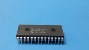
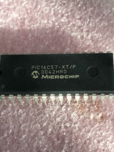
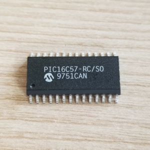
    Read MCU PIC16C57 Program deals with the recovery of firmware from a secured, protected, or locked microcontroller when no original development files or backup archive remain available. The PIC16C57 is based on OTP memory architecture, meaning the program is permanently embedded in the chip after programming. When systems require duplication, repair, or long-term maintenance, engineers must apply reverse engineering to open restricted access, extract a stable memory dump, and restore the firmware into a structured binary or heximal file. The priority is to recover a complete and accurate firmware archive that mirrors the original program stored in the microprocessor without introducing inconsistencies.

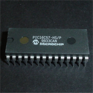
    Reading secured PIC16C57 program memory
    OTP PIC16C57 microcontroller during program read-out

    The PIC16C57 microcontroller is a practical 8-bit solution built around a simple yet efficient RISC architecture. It provides expanded I/O capability compared to smaller PIC variants, along with predictable instruction execution and reliable timing control. Although it lacks EEPROM and modern flash reprogramming features, it has been widely used in industrial automation devices, consumer control systems, automotive electronics, and security applications. In these deployments, the firmware stored within the chip functions as a permanent program archive, controlling system logic, signal processing, and device interaction. The MCU acts as both the computational unit and the storage medium for critical operational data.

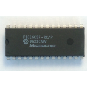
    OTP PIC16C57 microcontroller during program read-out
    PIC16C57 code protection fuse layout

    Read MCU PIC16C57 Program is a process to extract embedded firmware out from Microcontroller flash and eeprom memory, start from decapsulate the silicon package and delayer the whole structure, recover MCU code can fulfill the task of IC cloning; A fetch cycle begins with the program counter (PC) incrementing in Q1. In the execution cycle, the fetched instruction is latched into the Instruction Register (IR) in cycle Q1.

    This instruction is then decoded and executed during the Q2, Q3, and Q4 cycles. Data memory is read during Q2 (operand read) and written during Q4 (destination write) if MCU protection can be removed and code will be extracted. All instructions are single cycle, except for any program branches. These take two cycles since the fetch instruction is “flushed” from the pipeline while the new instruction is being fetched and then executed. PIC16C57 memory is organized into program memory and data memory. For devices with more than 512 bytes of program memory, a paging scheme is used.

    PIC16C57 code protection fuse layout
    Reading secured PIC16C57 program memory

    Program memory pages are accessed using one STATUS register bit. For the PIC16C57 with a data memory register file of more than 32 registers, a banking scheme is used. Data memory banks are accessed using the File Select Register (FSR). The PIC16C57 devices have a 12-bit Program Counter (PC) capable of addressing a 2K x 12 program memory space. Only the first 512 x 12 (0000h-01FFh) for the PIC16C57 and 1K x 12 (0000h-03FFh) for the PIC16C57 are physically implemented. Refer to Figure 4-1. Accessing a location above these boundaries will cause a wrap around within the first 512 x 12 space (PIC16C57) or 1K x 12 space (PIC16C57). The effective reset vector is at 000h, (see Figure 4-1). Location 01FFh (PIC16C57) or location 03FFh (PIC16C57) contains the internal clock oscillator calibration value. This value should never be overwritten.

    Reading secured PIC16C57 program memory
    OTP PIC16C57 microcontroller during program read-out

    Read MCU PIC16C57 Program processes often require engineers to hack into a secured MCU to extract, recover, restore, and reverse engineer firmware from its locked internal memory. Because the chip is protected against direct readout, the process must carefully open access to the program memory and obtain a reliable binary dump without compromising data integrity. Engineers then reconstruct a valid heximal file and organize the firmware archive into a usable format. Challenges include handling OTP-based memory limitations, overcoming read-protection mechanisms, and ensuring that the extracted data remains complete and accurate. Maintaining consistency across the recovered firmware is essential for successful restoration and future use.

    OTP PIC16C57 microcontroller during program read-out
    PIC16C57 code protection fuse layout

    Recovering firmware from a PIC16C57 microcontroller provides substantial benefits for clients maintaining legacy systems and long-lifecycle products. By restoring a usable binary or program file, organizations can replicate existing designs, repair obsolete equipment, and continue production without redesigning hardware or rewriting source code. The recovered firmware archive also supports advanced reverse engineering analysis, enabling engineers to understand system behavior, validate functionality, and rebuild missing software components when necessary. This approach reduces engineering costs, minimizes downtime, and preserves valuable intellectual property embedded within the chip. Ultimately, Read MCU PIC16C57 Program transforms a secured and inaccessible microcontroller into a reusable engineering asset, ensuring long-term operational continuity across various industries.