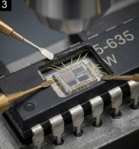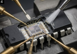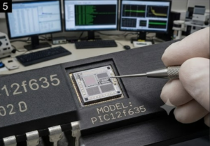
Modern embedded ecosystems increasingly rely on compact 8-bit architectures like the PIC12F635, a nanoWatt XLP microcontroller engineered specifically for ultra-low-power applications spanning automotive sensor nodes, residential security peripherals, and portable medical instrumentation. Unlike general-purpose microprocessors, this chip integrates a precision internal oscillator alongside high-performance analog comparators, making it exceptionally suited for battery-backed devices where extended field life outweighs raw computational demands.
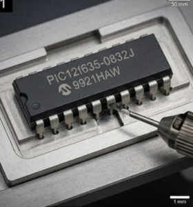
Industrial designers routinely deploy this MCU within tire-pressure monitoring systems, encrypted wireless key fobs, smart utility meters, and industrial process controllers—environments where the embedded program must survive voltage fluctuations, thermal cycling, and electromagnetic interference without corruption. Because the internal flash array and independent EEPROM retain factory calibration tables, proprietary control algorithms, and unique device identifiers, losing the original firmware archive effectively orphans entire hardware platforms, forcing maintenance teams to confront the reality that a locked chip can become an unopenable vault once its protection bits activate.
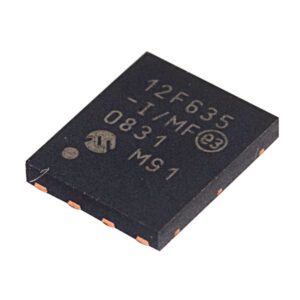
Setting a pin to an analog input automatically disables the digital input circuitry, weak pull-ups and interrupt-on-change if available. The corresponding TRIS bit must be set to Input mode in order to allow external control of the voltage on the pin. The Ultra Low-Power Wake-up (ULPWU) on RA0 allows a slow falling voltage to generate an interrupt-on-change on RA0 without excess current consumption. The mode is selected by setting the ULPWUE bit of the PCON register. This enables a small current sink, which can be used to discharge a capacitor on RA0. Follow these steps to use this feature:
Charge the capacitor on RA0 by configuring the
RA0 pin to output (= 1).
Configure RA0 as an input.
Enable interrupt-on-change for RA0.
Set the ULPWUE bit of the PCON register to begin the capacitor discharge. Execute a SLEEP instruction. When the voltage on RA0 drops below VIL, an interrupt will be generated which will cause the device to wake-up and execute the next instruction.
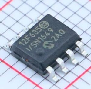
If the GIE bit of the INTCON register is set, the device will then call the interrupt vector (0004h). See Section 4.4.2 “Interrupt-on-change” and Section 14.3.3 “PORTA/PORTB Interrupt” for more information. This feature provides a low-power technique for periodically waking up the device from Sleep. The time-out is dependent on the discharge time of the RC circuit on RA0. See Example 4-2 for initializing the Ultra Low-Power Wake-up module.
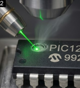
A series resistor between RA0 and the external capacitor provides overcurrent protection for the RA0/AN0/C1IN+/ICSPDAT/ULPWU pin and can allow for software calibration of the time-out. A timer can be used to measure the charge time and discharge time of the capacitor. The charge time can then be adjusted to provide the desired interrupt delay. This technique will compensate for the affects of temperature, voltage and component accuracy. The Ultra Low-Power Wake-up peripheral can also be configured as a simple Programmable Low-Voltage Detect or temperature sensor.