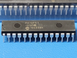
The PIC16F57 is a classic 8‑bit microcontroller from Microchip’s baseline family, widely deployed in automotive keyless entry systems, industrial timers, consumer remote controls, battery chargers, and simple medical diagnostic tools. It contains 3KB of FLASH program memory, 72 bytes of EEPROM data storage, and 72 bytes of SRAM. Despite its modest specifications, the chip is extremely reliable and cost‑effective, which is why millions of MCU units still operate in locked microprocessors inside obsolete or outdated equipment. Manufacturers often set protective fuses to prevent unauthorised readout of the binary file that drives the device. When the original source code is lost or the vendor no longer supports the product, the only remaining copy of the firmware is trapped inside the secured chip. Recovering it becomes a critical task for reverse engineering, maintenance, or product replication.
The Timer0 module has the following features:
- 8-bit timer/counter register, TMR0
– Readable and writable
- 8-bit software programmable prescaler
- Internal or external clock select
– Edge select for external clock
Figure 6-1 is a simplified block diagram of the Timer0 module.
Timer mode is selected by clearing the T0CS bit (OPTION<5>). In timer mode, the Timer0 module will increment every instruction cycle (without prescaler). If TMR0 register is written, the increment is inhibited for the following two instruction cycles (Figure 6-2 and Figure 6-3). The user can work around this by writing an adjusted value to the TMR0 register. Counter mode is selected by setting the T0CS bit (OPTION<5>). In this mode, Timer0 will increment either on every rising or falling edge of pin T0CKI. The T0SE bit (OPTION<4>) determines the source edge. Clearing the T0SE bit selects the rising edge. Restrictions on the external clock input are discussed in detail in Section 6.1.
The prescaler may be used by either the Timer0 module or the Watchdog Timer, but not both. The prescaler assignment is controlled in software by the control bit PSA (OPTION<3>). Clearing the PSA bit will assign the prescaler to Timer0. The prescaler is not readable or writable. When the prescaler is assigned to the Timer0 module, prescale values of 1:2, 1:4,…, 1:256 are selectable. Section 6.2 details the operation of the prescaler.
A summary of registers associated with the Timer0 When an external clock input is used for Timer0, it must meet certain requirements. The external clock requirement is due to internal phase clock (TOSC) synchronization. Also, there is a delay in the actual incrementing of Timer0 after synchronization. When no prescaler is used, the external clock input is the same as the prescaler output. The synchronization of T0CKI with the internal phase clocks is accomplished by sampling the prescaler output on the Q2 and Q4 cycles of the internal phase clocks. Therefore, it is necessary for T0CKI to be high for at least 2TOSC (and a small RC delay of 20 ns) and low for at least 2TOSC (and a small RC delay of 20 ns). Refer to the electrical specification of the desired device.
There is a legitimate, growing demand to copy the software from a protected PIC16F57. Why? Because many industrial controllers, automotive modules, and medical devices have become obsolete, yet they still perform essential functions. When the microcontroller fails, replacing it with a new, locked chip is impossible without the original heximal or binary program. Reverse engineering the memory allows engineers to extract the archive of machine code, recover the data, and restore the device to full operation. The alternative – redesigning the entire electronic system – can cost tens of thousands of dollars and months of development time. By performing a clean dump of the FLASH and EEPROM contents, we can open the secured microprocessor and produce an exact binary file that can be programmed into a fresh MCU. This process is not about piracy; it is about restoring functionality, preserving legacy investments, and avoiding unnecessary electronic waste.
The PIC16F57 implements encrypted protection through configurable lock bits (specifically the CP bit for code protection and the WRT bit for write protection). Once these bits are set, standard programmers refuse to readout the flash memory or dump the EEPROM archive. A simple copy command returns only zeros. Hack or extract attempts using software alone are impossible because the chip physically blocks external readout when the lock is active. To recover the firmware, one must overcome these protective mechanisms without destroying the microcontroller. This requires advanced techniques such as decapsulation, micro‑probing, or fault injection – methods that are time‑consuming and require specialised equipment. Many service providers fail because they lack the expertise to differentiate between a secured chip that can be opened and one that has been permanently locked by fusing. Our approach is non‑destructive in most cases, preserving the original microprocessor for future analysis while delivering a complete binary or heximal file.
We offer a reliable, confidential service to copy software from secured PIC16F57 microcontrollers and other legacy MCU families. Whether you need to dump the flash memory, recover a lost program, or reverse engineer an encrypted archive, our engineers deliver a clean binary or heximal file ready for reprogramming. We handle obsolete chips that official distributors no longer support. Benefits to clients include: rapid turnaround, preservation of intellectual property, avoidance of costly hardware redesigns, and the ability to extend product lifecycles for years. Contact us with your locked microcontroller – we will open it, extract the firmware, and return a fully functional copy that matches the original software exactly.