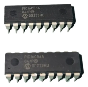
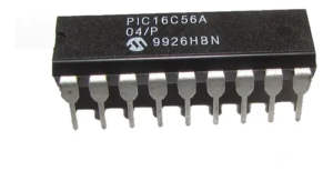
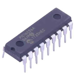
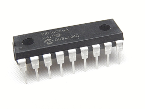
The PIC16C56A microcontroller remains a widely deployed 8-bit MCU in legacy industrial and embedded systems due to its reliability, compact architecture, and cost efficiency. Built on a Harvard architecture with OTP (one-time programmable) memory, this chip is commonly found in consumer electronics, automotive control modules, home appliances, and industrial controllers. Despite its relatively simple design compared to modern microprocessors, the PIC16C56A often contains critical firmware and proprietary program logic stored in internal memory. In many cases, manufacturers enable secured or locked protection mechanisms to prevent unauthorized access, making it difficult to directly open or read out the binary or heximal data from the chip.
From a technical perspective, the process to hack, extract, recover, or restore data from a protected PIC16C56A involves overcoming multiple layers of embedded security. These microcontrollers are designed with protection bits that lock access to internal memory, preventing straightforward dumping of firmware, EEPROM, or program data. Reverse engineering such a secured MCU requires specialized approaches to bypass encrypted or locked states without damaging the silicon. Engineers aiming to extract a binary file or archive must deal with challenges such as read protection fuses, signal obfuscation, and potential data corruption during access attempts. The objective is to safely retrieve the memory contents—including source code, program structure, and embedded data—while preserving integrity for further analysis or reproduction.
Extract IC PIC16C56A Binary out from its secured memory include flash and eeprom, copy the code into blank microcontroller after crack original MCU security fuse bits. Data memory is composed of registers, or bytes of RAM. Therefore, data memory for a device is specified by its register file. The register file is divided into two functional groups: special function registers and general purpose registers. The special function registers include the TMR0 register, the Program Counter (PC), the Status Register, the I/O registers (ports), and the File Select Register (FSR) when preventing microcontroller copying. In addition, special purpose registers are used to control the I/O port configuration and prescaler options. The general purpose registers are used for data and control information under command of the instructions.
For the PIC16C56A, the register file is composed of 7 special function registers and 25 general purpose registers. The Special Function Registers (SFRs) are registers used by the CPU and peripheral functions to control the operation of the device The special registers can be classified into two sets. The special function registers associated with the “core” functions are described in this section. Those related to the operation of the peripheral features are described in the section for each peripheral feature. This register contains the arithmetic status of the ALU, the RESET status, and the page preselect bit for program memories larger than 512 words. The OPTION register is a 8-bit wide, write-only register which contains various control bits to configure the Timer0/WDT prescaler and Timer0. By executing the OPTION instruction, the contents of the W register will be transferred to the OPTION register. A RESET sets the OPTION<7:0> bits.
In practical applications, the ability to reverse engineering and duplicate or restore a PIC16C56A chip’s firmware brings significant value. For instance, when original documentation, source code, or design archives are lost, companies may need to recover the binary or heximal file to maintain or refurbish existing equipment. This is especially critical in industries where legacy systems are still operational but no longer supported by the original manufacturer. By extracting and reconstructing the program and memory data, it becomes possible to recreate or replicate the chip’s functionality, ensuring continuity of production lines or repair services. Additionally, analyzing the firmware can provide insights into system behavior, enabling optimization or redesign of outdated hardware platforms.
Ultimately, the importance of extracting data from a secured microcontroller like the PIC16C56A lies in its practical and commercial benefits. Clients gain the ability to restore critical firmware, rebuild lost archives, and extend the lifecycle of valuable equipment. While the chip is protected and often encrypted to prevent unauthorized duplication, professional reverse engineering services can carefully navigate these barriers to recover essential data. This capability supports product maintenance, cost reduction, and technological continuity, particularly in sectors where replacing entire systems is not feasible. By leveraging controlled and ethical extraction techniques, businesses can unlock the full potential of their legacy MCU assets without compromising operational stability.