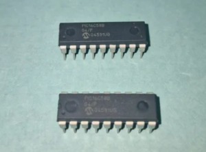
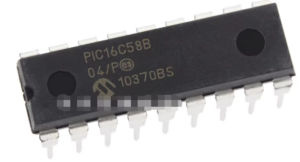
The PIC16C58B microcontroller is a classic 8-bit MCU widely recognized for its robustness and simplicity in embedded control applications. Based on a Harvard architecture and typically configured with one-time programmable memory, this chip has been extensively deployed across consumer electronics, automotive subsystems, industrial automation controllers, and household appliances. Despite its age, the PIC16C58B remains deeply integrated in many long-lifecycle products where stable firmware execution is critical. Manufacturers often implement secured or protected configurations within the chip to lock internal memory, ensuring that the program, firmware, and operational data remain inaccessible to unauthorized parties. As a result, attempting to open or directly read the binary or heximal file stored in such a locked MCU becomes a non-trivial engineering challenge.
Bằng cách áp dụng các phương pháp được kiểm soát để trích xuất và khôi phục dữ liệu nhị phân hoặc thập lục phân từ vi điều khiển Microchip PIC16C58B được bảo mật, các công ty có thể xây dựng lại các tệp chương trình quan trọng và khôi phục các cấu trúc bộ nhớ thiết yếu. Điều này cho phép các kỹ sư sao chép hoặc nhân bản hoạt động của vi điều khiển Microchip PIC16C58B, tân trang thiết bị hiện có và thậm chí chuyển chức năng sang các nền tảng vi xử lý hoặc vi điều khiển mới hơn. Hơn nữa, việc phân tích phần mềm được khôi phục cung cấp những hiểu biết có giá trị về logic hệ thống, cho phép tối ưu hóa, gỡ lỗi hoặc thiết kế lại các hệ thống điện tử cũ. Về mặt kỹ thuật, làm việc với vi xử lý Microchip PIC16C58B được bảo mật, khóa hoặc mã hóa có nhiều lớp phức tạp cần được giải quyết cẩn thận. Quá trình trích xuất có thể liên quan đến việc vượt qua các cơ chế bảo vệ được nhúng trong kiến trúc MCU Microchip PIC16C58B được mã hóa, đảm bảo rằng bản sao phần mềm, dữ liệu bộ nhớ và kho lưu trữ chương trình được bảo toàn chính xác. Những thách thức như sự không ổn định của tín hiệu, rủi ro về tính toàn vẹn dữ liệu và trạng thái khóa không thể đảo ngược đòi hỏi độ chính xác và kinh nghiệm. Tuy nhiên, lợi ích của việc khôi phục và phục hồi dữ liệu thành công là rất đáng kể.
In advanced technical scenarios, the demand to hack, extract, recover, restore, or reverse engineering a secured PIC16C58B microcontroller arises when original firmware, source code, or design archive is no longer available. Engineers must deal with protected or encrypted states that prevent direct access to internal memory, flash regions, or embedded data structures. The process of extracting a binary dump or reconstructing a program file involves navigating hardware-level restrictions such as read-protection bits, disabled programming interfaces, and integrity safeguards. Accessing the MCU memory safely requires specialized handling to avoid data corruption, especially when attempting to retrieve EEPROM content, firmware logic, or archived program data from a locked chip. Each step must ensure that the recovered data remains consistent and usable for further analysis or redevelopment.
Застосовуючи контрольовані методи для вилучення та відновлення двійкових або шістнадцяткових даних із захищеного мікроконтролера Microchip PIC16C58B, компанії можуть перебудовувати критично важливі програмні файли та відновлювати важливі структури пам’яті. Це дозволяє інженерам дублювати або реплікувати поведінку мікроконтролера Microchip PIC16C58B, оновлювати існуюче обладнання та навіть переносити функціональність на новіші мікропроцесорні або мікроконтролерні платформи. Крім того, аналіз відновленого мікропрограмного забезпечення надає цінну інформацію про логіку системи, що дозволяє оптимізувати, налагоджувати або перепроектувати старіючі електронні системи. Технічно, робота із захищеним, заблокованим або зашифрованим мікропроцесором Microchip PIC16C58B представляє кілька рівнів складності, які необхідно ретельно розглядати. Процес вилучення може включати подолання механізмів захисту, вбудованих у зашифровану архітектуру мікроконтролера Microchip PIC16C58B, що забезпечує точне збереження дампа мікропрограми, даних пам’яті та архіву програм. Такі проблеми, як нестабільність сигналу, ризики цілісності даних та незворотні стани блокування, вимагають точності та досвіду. Однак переваги успішного відновлення таких даних є значними.
Copy Microcontroller PIC16C58B Program out from memory include the flash and eeprom, the heximal extracted can be reprogrammed to other blank MCU which will provide the same functions as original version; PIC16C58B devices have a 12-bit wide L.I.F.O. hardware push/pop stack. A CALL instruction will push the current value of stack 1 into stack 2 and then push the current program counter value, incremented by one, into stack level 1.
If more than two sequential CALL’s are executed, only the most recent two return addresses are stored. ARETLW instruction will pop the contents of stack level 1 into the program counter and then copy stack level 2 contents into level 1. If more than two sequential RETLW’s are executed, the stack will be filled with the address previously stored in level 2. Note that the W register will be loaded with the literal value specified in the instruction. This is particularly useful for the implementation of data look-up tables within the program memory. Upon any reset, the contents of the stack remain unchanged, however the program counter (PCL) will also be reset to 0.
सिक्योर्ड MCU माइक्रोचिप PIC16C58B से बाइनरी या हेक्सिमल डेटा निकालने और रिस्टोर करने के लिए कंट्रोल्ड तरीकों का इस्तेमाल करके, कंपनियाँ ज़रूरी प्रोग्राम फ़ाइलों को फिर से बना सकती हैं और ज़रूरी मेमोरी स्ट्रक्चर को रिकवर कर सकती हैं। इससे इंजीनियर माइक्रोचिप PIC16C58B माइक्रोकंट्रोलर के बिहेवियर को डुप्लिकेट या कॉपी कर सकते हैं, मौजूदा इक्विपमेंट को रिफर्बिश कर सकते हैं, और यहाँ तक कि नए माइक्रोप्रोसेसर या माइक्रोकंट्रोलर प्लेटफॉर्म में फंक्शनैलिटी को माइग्रेट भी कर सकते हैं। इसके अलावा, रिकवर किए गए फर्मवेयर का एनालिसिस करने से सिस्टम लॉजिक के बारे में कीमती जानकारी मिलती है, जिससे पुराने इलेक्ट्रॉनिक सिस्टम को ऑप्टिमाइज़, डीबग या रीडिज़ाइन किया जा सकता है। टेक्निकली, एक सिक्योर्ड, लॉक्ड या एन्क्रिप्टेड माइक्रोचिप PIC16C58B माइक्रोप्रोसेसर के साथ काम करने में कई मुश्किलें आती हैं जिन्हें ध्यान से देखना चाहिए। एक्सट्रैक्शन प्रोसेस में एन्क्रिप्टेड माइक्रोचिप PIC16C58B MCU आर्किटेक्चर में एम्बेडेड प्रोटेक्शन मैकेनिज्म को पार करना शामिल हो सकता है, जिससे यह पक्का हो सके कि फर्मवेयर डंप, मेमोरी डेटा और प्रोग्राम आर्काइव सही तरीके से सुरक्षित हैं। सिग्नल इनस्टेबिलिटी, डेटा इंटीग्रिटी रिस्क और इर्रिवर्सिबल लॉक स्टेट्स जैसी चुनौतियों के लिए सटीकता और अनुभव की ज़रूरत होती है। हालाँकि, ऐसे डेटा को सफलतापूर्वक रिकवर और रिस्टोर करने के फायदे बहुत ज़्यादा हैं।
The INDF register is not a physical register. Addressing INDF actually addresses the register As with any other register, the I/O register can be written and read under program control. However, read instructions (e.g., MOVF GPIO,W) always read the I/O pins independent of the pin’s input/output modes. On RESET, all I/O ports are defined as input (inputs are at hi-impedance) since the I/O control registers are all set. See Section 7.0 for SCL and SDA description for PIC16C58B. GPIO is an 8-bit I/O register. Only the low order 6 bits are used (GP5:GP0). Bits 7 and 6 are unimplemented and read as ‘0’s.
Применяя контролируемые методы для извлечения и восстановления двоичных или шестнадцатеричных данных из защищенного микроконтроллера Microchip PIC16C58B, компании могут восстанавливать критически важные программные файлы и основные структуры памяти. Это позволяет инженерам дублировать или воспроизводить поведение микроконтроллера Microchip PIC16C58B, модернизировать существующее оборудование и даже переносить функциональность на более новые платформы микропроцессоров или микроконтроллеров. Кроме того, анализ восстановленной прошивки предоставляет ценную информацию о логике системы, позволяя оптимизировать, отлаживать или перепроектировать устаревающие электронные системы. С технической точки зрения, работа с защищенным, заблокированным или зашифрованным микропроцессором Microchip PIC16C58B сопряжена с множеством сложностей, которые необходимо тщательно учитывать. Процесс извлечения может включать в себя преодоление механизмов защиты, встроенных в зашифрованную архитектуру микроконтроллера Microchip PIC16C58B, обеспечивая точное сохранение дампа прошивки, данных памяти и архива программы. Такие проблемы, как нестабильность сигнала, риски целостности данных и необратимые состояния блокировки, требуют точности и опыта. Однако преимущества успешного восстановления таких данных весьма существенны.
Please note that GP3 is an input only pin. The configuration word can set several I/O’s to alternate functions. When acting as alternate functions the pins will read as ‘0’ during port read. Pins GP0, GP1, and GP3 can be configured with weak pull-ups and also with wake-up on change. The wake-up on change and weak pull-up functions are not pin selectable. If pin 4 is configured as MCLR, weak pull-up is always on and wake-up on change for this pin is not enabled.
From an operational standpoint, the ability to reverse engineering and copy a PIC16C58B program delivers significant advantages in industrial maintenance and product lifecycle management. Many legacy systems still rely on this microcontroller, yet their original source code, firmware archive, or technical documentation may be lost due to time or vendor discontinuation. By applying controlled methods to extract and restore binary or heximal data from the MCU, companies can rebuild critical program files and recover essential memory structures. This allows engineers to duplicate or replicate the chip’s behavior, refurbish existing equipment, and even migrate functionality into newer microprocessor or microcontroller platforms. Furthermore, analyzing the recovered firmware provides valuable insights into system logic, enabling optimization, debugging, or redesign of aging electronic systems.