
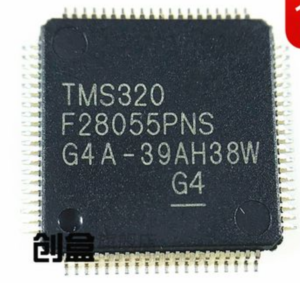
Three independent mechanisms stand between a stranger and the program inside a TMS320F28055. A 128-bit password guards each of two memory zones. A control law accelerator runs a second instruction stream out of the protected array. And a boot configuration decides which interface the part will listen to after reset. Sixty-four thousand words of flash and ten thousand of SARAM sit under all of that, at sixty megahertz, with fourteen PWM channels and sixteen ADC inputs.
Layer One: The Zones
Zone 1 and Zone 2 are configured in OTP and carry separate passwords. A readout that opens Zone 1 sees the application and nothing else; the region belonging to Zone 2 reads as protected regardless of how the probe is placed, because the protection is enforced by the memory controller rather than by the array layout.
The practical implication is that a dual-zone job is quoted in two parts. When both passwords are recoverable the job is straightforward; when neither is, the die is opened once and both ranges are read physically in the same session, which is cheaper than two visits but more expensive than one password.
Layer Two: The Second Core
The accelerator’s task code lives in the same array as the main program and is subject to the same zone rules. If the accelerator code happens to be in the zone that opened, it comes back with everything else; if it sits in the other zone, the image has a hole exactly where the control algorithm was.
Those holes are the hardest part of the reconstruction. A hole in the middle of a C28x routine is visible — the disassembly stops making sense. A hole where a CLA task should be is invisible until the task is triggered, which does not happen during a boot test. We check the task table against the code around it and report any entry that points into an unread region.
Layer Three: The Boot Configuration
The boot pins decide whether the part comes up in wait mode, boots from flash, or enters a loader over SCI, SPI, CAN or I2C. That configuration matters for two reasons. It tells us how the part was programmed at the factory, which is a hint about where the password came from. And it determines whether a rebuilt image can be tested without a debugger attached at all — a flash-boot part can be validated on a bare board, which is often the only kind of board a customer has.
Changing the boot mode during test is legitimate and reversible; it is written to a shadow register, not to OTP.
What A Failed Attempt Leaves Behind
A meaningful share of the units that reach this bench have already been opened somewhere else. The results vary. A clean decapsulation that stopped at the passivation is workable. A package milled too deep, with two bond wires lifted, is usually still workable if the broken wires are not on the array side. A die with probe marks across the flash macro is the difficult case, because the marks are physical damage and every subsequent contact reads a cell that may have been disturbed.
We photograph the die before touching it and compare the pad condition with what a first-pass unit looks like. That comparison decides whether the job proceeds, whether it proceeds with a reduced scope, or whether the honest answer is that the part has been destroyed. Customers generally prefer that answer early to a partial image late.
The Order Of Work
OTP configuration is read first, because it defines the zones and the boot mode without revealing secrets. Then the passwords are attempted from every available source. If that fails, the package is opened and the array is read in one pass, with the zone boundaries taken from the OTP map rather than inferred.
Reconstruction then proceeds outward from the vector table, with the task table handled as a separate stream. The parameter area comes last, checked against physical plausibility rather than against the code.
What Makes This Part Worth Documenting
A design that used all three layers is a design where the firmware was the product. That is why the report for this device runs longer than for its siblings: it states which zones opened, whether the accelerator code was reached, which boot path the original part used, and which checks passed on the rebuilt unit.
The same architecture at 64 KB is the TMS320F28053 job, and the version without the accelerator is covered on the TMS320F28054 page. Scope and quantity through the services desk or the contact form.