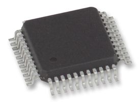
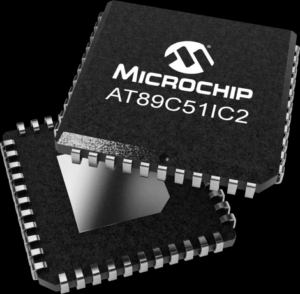
The AT89C51IC2 is a high-performance CMOS Flash version of the 80C51 CMOS single-chip 8-bit microcontroller developed by Atmel (now Microchip). This microcontroller contains a 64KB Flash memory block for program and data storage, making it suitable for various industrial applications 3. Unlike standard AT89C51 variants with only 4KB Flash memory, the AT89C51IC2 offers significantly more storage capacity while maintaining compatibility with the MCS-51 instruction set.
Extract Microcontroller AT89C51IC2 Program from embedded flash and eeprom, unlock mcu at89c5ic2 protection and recover heximal from processor at89c51ic2;
The CMOD register includes three additional bits associated with the PCA (See Figure 11 and Table 26).
The CIDL bit which allows the PCA to stop during idle mode.
The WDTE bit which enables or disables the watchdog function on module 4.
The ECF bit which when set causes an interrupt and the PCA overflow flag CF (in the CCON SFR) to be set when the PCA timer overflows.
The CCON register contains the run control bit for the PCA and the flags for the PCA timer (CF) and each module (Refer to Table 27).
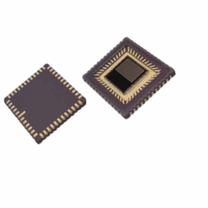
1. Dekapsulacja i mikroprobowanie
Fizyczna dekapsulacja obudowy układu scalonego za pomocą trawienia chemicznego lub trawienia plazmowego odsłania krzemową matrycę. Po odsłonięciu techniki mikroprobowania mogą bezpośrednio uzyskać dostęp do komórek pamięci i magistrali w celu wyodrębnienia danych binarnych. Ta metoda omija zabezpieczenia programowe, ale wymaga specjalistycznego sprzętu i wiedzy.
2. Ataki analizy mocy
Analiza mocy różnicowej (DPA) i prosta analiza mocy (SPA) mogą ujawnić klucze szyfrujące i zawartość pamięci poprzez monitorowanie zużycia energii przez układ podczas pracy. Te nieinwazyjne ataki są skuteczne przeciwko niektórym chronionym mikrokontrolerom.
3. Techniki wstrzykiwania błędów
Wprowadzając kontrolowane zakłócenia napięcia lub zakłócenia zegara, można czasami ominąć mechanizmy bezpieczeństwa, umożliwiając dostęp do chronionych obszarów pamięci. Ta metoda wymaga precyzyjnego pomiaru czasu i rozległych testów.
4. Ataki światłem UV
Niektóre starsze wersje układów scalonych z rodziny 8051 były podatne na wymazywanie bitów bezpieczeństwa światłem UV. Chociaż nowoczesne układy scalone, takie jak AT89C51IC2, mają ulepszoną ochronę, nadal można spróbować tej metody.
5. Eksploatacja interfejsu JTAG i debugowania
Jeśli interfejsy debugowania są włączone lub można je aktywować, mogą one zapewniać bezpośredni dostęp do pamięci. Wiele nowoczesnych układów scalonych wyłączyło te interfejsy w jednostkach produkcyjnych, ale czasami istnieją luki w zabezpieczeniach.
Methods for Extracting Protected Firmware
1. Decapsulation and Microprobing
Physical decapsulation of the chip package using chemical etching or plasma etching exposes the silicon die. Once exposed, microprobing techniques can directly access memory cells and buses to extract binary data. This method bypasses software protections but requires specialized equipment and expertise.
2. Power Analysis Attacks
Differential Power Analysis (DPA) and Simple Power Analysis (SPA) can reveal encryption keys and memory contents by monitoring the chip’s power consumption during operation. These non-invasive attacks are effective against some protected microcontrollers.
1. Decapsulamento e Microsondagem
O decapsulamento físico do encapsulamento do chip usando corrosão química ou corrosão por plasma expõe o chip de silício. Uma vez exposto, as técnicas de microsondagem podem acessar diretamente as células e os barramentos de memória para extrair dados binários. Este método contorna as proteções de software, mas requer equipamento especializado e conhecimento especializado.
2. Ataques de Análise de Potência
A Análise Diferencial de Potência (DPA) e a Análise Simples de Potência (SPA) podem revelar chaves de criptografia e o conteúdo da memória monitorando o consumo de energia do chip durante a operação. Esses ataques não invasivos são eficazes contra alguns microcontroladores protegidos.
3. Técnicas de Injeção de Falhas
Ao introduzir falhas de tensão controladas ou distúrbios de clock, os mecanismos de segurança podem, às vezes, ser contornados, permitindo o acesso a áreas de memória protegidas. Este método requer temporização precisa e testes extensivos.
4. Ataques de Luz UV
Algumas versões mais antigas dos chips da família 8051 eram vulneráveis à eliminação de bits de segurança por luz UV. Embora chips modernos como o AT89C51IC2 tenham proteção aprimorada, esse método ainda pode ser tentado.
5. Exploração de JTAG e Interface de Depuração
Se as interfaces de depuração estiverem habilitadas ou puderem ser ativadas, elas podem fornecer acesso direto à memória. Muitos chips modernos desabilitaram essas interfaces em unidades de produção, mas às vezes existem vulnerabilidades.
3. Fault Injection Techniques
By introducing controlled voltage glitches or clock disturbances, security mechanisms can sometimes be bypassed, allowing access to protected memory areas. This method requires precise timing and extensive testing.
4. UV Light Attacks
Some older versions of 8051-family chips were vulnerable to UV light erasure of security bits. While modern chips like AT89C51IC2 have improved protection, this method may still be attempted.
5. JTAG and Debug Interface Exploitation
If debug interfaces are enabled or can be activated, they may provide direct memory access. Many modern chips have disabled these interfaces in production units, but vulnerabilities sometimes exist.
2. Power Analysis Attacks
Differential Power Analysis (DPA) and Simple Power Analysis (SPA) can reveal encryption keys and memory contents by monitoring the chip’s power consumption during operation. These non-invasive attacks are effective against some protected microcontrollers.
3. Fault Injection Techniques
By introducing controlled voltage glitches or clock disturbances, security mechanisms can sometimes be bypassed, allowing access to protected memory areas. This method requires precise timing and extensive testing.
4. UV Light Attacks
Some older versions of 8051-family chips were vulnerable to UV light erasure of security bits. While modern chips like AT89C51IC2 have improved protection, this method may still be attempted.
5. JTAG and Debug Interface Exploitation
If debug interfaces are enabled or can be activated, they may provide direct memory access. Many modern chips have disabled these interfaces in production units, but vulnerabilities sometimes exist.
1. Декапсуляция и микрозондирование
Физическая декапсуляция корпуса чипа с использованием химического травления или плазменного травления обнажает кремниевый кристалл. После вскрытия методы микрозондирования могут напрямую получить доступ к ячейкам памяти и шинам для извлечения двоичных данных. Этот метод обходит программную защиту, но требует специального оборудования и опыта.
2. Атаки с использованием анализа питания
Дифференциальный анализ питания (DPA) и простой анализ питания (SPA) могут раскрыть ключи шифрования и содержимое памяти, отслеживая энергопотребление чипа во время работы. Эти неинвазивные атаки эффективны против некоторых защищенных микроконтроллеров.
3. Методы внесения неисправностей
Внедряя контролируемые сбои напряжения или нарушения синхронизации, иногда можно обойти механизмы безопасности, что позволяет получить доступ к защищенным областям памяти. Этот метод требует точного времени и обширного тестирования.
4. Атаки с использованием УФ-излучения
Некоторые старые версии чипов семейства 8051 были уязвимы к стиранию битов безопасности с помощью УФ-излучения. Хотя современные чипы, такие как AT89C51IC2, имеют улучшенную защиту, этот метод все еще может быть использован.
5. Эксплуатация JTAG и отладочного интерфейса
Если отладочные интерфейсы включены или могут быть активированы, они могут обеспечить прямой доступ к памяти. Многие современные чипы отключили эти интерфейсы в производственных единицах, но уязвимости иногда существуют.
Bit CR (CCON.6) must be set by software to run the PCA. The PCA is shut off by clearing this bit.
Bit CF: The CF bit (CCON.7) is set when the PCA counter overflows and an interrupt will be generated if the ECF bit in the CMOD register is set. The CF bit can only be cleared by software.
Bits 0 through 4 are the flags for the modules (bit 0 for module 0, bit 1 for module 1, etc.) and are set by hardware when either a match or a capture occurs. These flags also can only be cleared by software if Extract MCU protection.
Each module in the PCA has a special function register associated with it. These registers are: CCAPM0 for module 0, CCAPM1 for module 1, etc. (See Table 28). The registers contain the bits that control the mode that each module will operate in.
The ECCF bit (CCAPMn.0 where n=0, 1, 2, 3, or 4 depending on the module) enables the CCF flag in the CCON SFR to generate an interrupt when a match or compare occurs in the associated module.
-
Disassembly: Convert machine code to assembly language using tools like IDA Pro or Ghidra
-
Control Flow Analysis: Reconstruct program logic and identify key functions
-
String Extraction: Recover human-readable strings and constants
-
Algorithm Reconstruction: Identify and document cryptographic or proprietary algorithms
-
Functionality Emulation: Test reconstructed code in emulators like Proteus
PWM (CCAPMn.1) enables the pulse width modulation mode. The TOG bit (CCAPMn.2) when set causes the CEX output associated with the module to toggle when there is a match between the PCA counter and the module’s capture/compare register after Extract Microcontroller code .
The match bit MAT (CCAPMn.3) when set will cause the CCFn bit in the CCON register to be set when there is a match between the PCA counter and the module’s capture/compare register.
The next two bits CAPN (CCAPMn.4) and CAPP (CCAPMn.5) determine the edge that a capture input will be active on. The CAPN bit enables the negative edge, and the CAPP bit enables the positive edge. If both bits are set both edges will be enabled and a capture will occur for either transition before Extract at89s53 Microcontroller.
The last bit in the register ECOM (CCAPMn.6) when set enables the comparator function.
To use one of the PCA modules in the capture mode either one or both of the CCAPM bits CAPN and CAPP for that module must be set. The external CEX input for the module (on port 1) is sampled for a transition. When a valid transition occurs the PCA hardware loads the value of the PCA counter registers (CH and CL) into the module’s capture registers (CCAPnL and CCAPnH). If the CCFn bit for the module in the CCON SFR and the ECCFn bit in the CCAPMn SFR are set then an interrupt will be generated
(Refer to Figure 13).
The PCA modules can be used as software timers by setting both the ECOM and MAT bits in the modules CCAPMn register. The PCA timer will be compared to the module’s capture registers and when a match occurs an interrupt will occur if the CCFn (CCON SFR) and the ECCFn (CCAPMn SFR) bits for the module are both set (See Figure 14).