Extract Microcontroller ATmega644P Code is a professional service centered on retrieving binary and heximal files from a secured and locked ATmega644P chip when standard programming interfaces can no longer open its internal memory. In embedded systems, the firmware stored inside flash memory is the operational backbone of the product, defining communication stacks, control algorithms, and safety routines. When protection fuse bits are enabled, access to EEPROM, flash, and other memory regions becomes restricted, effectively blocking direct readout of program data. Through structured reverse engineering processes, engineers can extract, recover, and restore critical firmware archives from a protected MCU while maintaining data integrity and minimizing risk to the microcontroller.
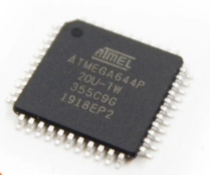
The ATmega644P microcontroller is widely recognized for its balanced architecture and robust peripheral integration. Built on the AVR 8-bit RISC platform, this MCU offers substantial flash program space, EEPROM for non-volatile parameter storage, and SRAM for dynamic data handling. It integrates multiple timers, PWM channels, SPI, USART, and TWI communication interfaces, as well as analog-to-digital conversion modules. These capabilities make the chip suitable for industrial automation controllers, smart metering systems, HVAC control boards, security panels, agricultural monitoring devices, and specialized consumer electronics. In such deployments, the microprocessor executes embedded firmware that manages real-time signals, processes sensor input, and coordinates external modules. The internal memory structure effectively serves as a digital archive of the system’s operational intelligence.
Extract Microcontroller ATmega644P Code from embedded program memory, the heximal can be completely recovered from MCU ATmega644P memory, and the status of MCU ATmega644P will be reset to unlocked one;
This bit is set when a time-out occurs in the Watchdog Timer and the Watchdog Timer is configured for interrupt. WDIF is cleared by hardware when executing the corresponding interrupt handling vector.
Alternatively, WDIF is cleared by writing a logic one to the flag. When the I-bit in SREG and WDIE are set, the Watchdog Time-out Interrupt is executed.
- Bit 6 – WDIE: Watchdog Interrupt Enable
When this bit is written to one and the I-bit in the Status Register is set, the Watchdog Interrupt is enabled. If WDE is cleared in combination with this setting, the Watchdog Timer is in Interrupt Mode, and the corresponding interrupt is executed if time-out in the Watchdog Timer occurs.
If WDE is set, the Watchdog Timer is in Interrupt and System Reset Mode. The first time-out in the Watchdog Timer will set WDIF. Executing the corresponding interrupt vector will clear WDIE and WDIF automatically by hardware (the Watchdog goes to System Reset Mode).
This is useful for keeping the Watchdog Timer security while using the interrupt. To stay in Interrupt and System Reset Mode, WDIE must be set after each interrupt. This should however not be done within the interrupt service routine itself, as this might compromise the safety-function of the Watchdog System Reset mode.
If the interrupt is not executed before the next time-out, a System Reset will be applied. This bit is used in timed sequences for changing WDE and prescaler bits. To clear the WDE bit, and/or change the prescaler bits, WDCE must be set.
Once written to one, hardware will clear WDCE after four clock cycles.
- Bit 3 – WDE: Watchdog System Reset Enable
WDE is overridden by WDRF in MCUSR. This means that WDE is always set when WDRF is set. To clear WDE, WDRF must be cleared first. This feature ensures multiple resets during conditions causing failure, and a safe start-up after the failure.
- Bit 5, 2..0 – WDP3..0: Watchdog Timer Prescaler 3, 2, 1 and 0
The WDP3..0 bits determine the Watchdog Timer prescaling when the Watchdog Timer is running. The different prescaling values and their corresponding time-out periods are shown in Table 28 on page 68.
Table 30 shows reset and Interrupt Vectors placement for the various combinations of BOOTRST and IVSEL settings. If the program never enables an interrupt source, the Interrupt Vectors are not used, and regular program code can be placed at these locations.
This is also the case if the Reset Vector is in the Application section while the Interrupt Vectors are in the Boot section or vice versa.
When the IVSEL bit is cleared (zero), the Interrupt Vectors are placed at the start of the Flash memory. When this bit is set (one), the Interrupt Vectors are moved to the beginning of the Boot Loader section of the Flash. The actual address of the start of the Boot Flash Section is determined by the BOOTSZ Fuses.
Refer to the section “Memory Programming” on page 335 for details. To avoid unintentional changes of Interrupt Vector tables, a special write procedure must be followed to change the IVSEL bit:
Interrupts will automatically be disabled while this sequence is executed. Interrupts are disabled in the cycle IVCE is set, and they remain disabled until after the instruction following the write to IVSEL. If IVSEL is not written, interrupts remain disabled for four cycles.
The I-bit in the Status Register is unaffected by the automatic disabling.
Note:
If Interrupt Vectors are placed in the Boot Loader section and Boot Lock bit BLB02 is programmed, interrupts are disabled while executing from the Application section. If Interrupt Vectors are placed in the Application section and Boot Lock bit BLB12 is programed, interrupts are disabled while executing from the Boot Loader section. Refer to the section “Memory Programming” on page 335 for details on Boot Lock bits.
- Bit 0 – IVCE: Interrupt Vector Change Enable
The IVCE bit must be written to logic one to enable change of the IVSEL bit. IVCE is cleared by hardware four cycles after it is written or when IVSEL is written. Setting the IVCE bit will disable interrupts, as explained in the IVSEL description above. See Code Example below.
Extract Microcontroller ATmega644P Code projects often become necessary when original source code or firmware files are lost, yet the secured device must continue operating or be upgraded. Attempting to hack or open a protected MCU presents considerable technical difficulty. The chip may be encrypted, fuse-locked, or configured to trigger memory erase functions upon unauthorized access. Reverse engineering a locked ATmega644P requires precise understanding of its flash organization, EEPROM mapping, bootloader configuration, and read-protection mechanisms. Extracting a consistent binary dump or heximal file from secured memory without corrupting program data demands controlled laboratory conditions and advanced analytical techniques. Challenges include maintaining signal stability, preventing unintended data overwrite, and ensuring that the recovered firmware archive remains structurally complete for further analysis or restoration.
The strategic value of extracting code from a protected ATmega644P chip extends beyond simple data retrieval. By recovering firmware and restoring program memory files, clients can resume stalled production, repair legacy equipment, and migrate designs to newer microcontroller platforms. Access to a verified memory dump also supports compliance audits, functional verification, and performance optimization. Instead of redesigning a complex embedded system from the ground up, organizations can leverage restored binary data and reconstructed source-level logic to preserve prior development investment. Ultimately, Extract Microcontroller ATmega644P Code services transform a locked and inaccessible MCU into a recoverable technical resource, strengthening business continuity and extending the lifecycle of mission-critical embedded products.