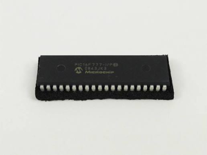
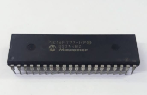
In modern industrial facilities, complex automation systems often rely on specialized embedded components that operate continuously behind the scenes. When a critical control board suffers physical failure and the original development documentation is missing, the specialized technical ability to read microcontroller pic16f777 heximal data becomes a vital strategy for business continuity. The PIC16F777 is a versatile 40-pin 8-bit device featuring an integrated 10-bit analog-to-digital converter (ADC) with up to 14 channels, multiple capture/compare/PWM (CCP) modules, and flexible serial communications interfaces.
Thanks to its high pin count, low operating power, and deterministic timing controls, equipment designers historically integrated this specific mcu into heavy industrial textile machinery, commercial building environmental regulators, automated bottling lines, and medical fluid monitoring instruments. However, when these aging control assemblies face forced component retirement, engineering teams must find a non-destructive path to access the core software instructions to prevent total operational failure.
The system clock is used if the Timer2 prescaler is set to 1:1. The resolution determines the number of available duty cycles for a given period. For example, a 10-bit resolution will result in 1024 discrete duty cycles, whereas an 8-bit resolution will result in 256 discrete duty cycles. The maximum PWM resolution is 10 bits when PR2 is The resolution is a function of the PR2 register value as shown by Equation 11-In Sleep mode, the TMR2 register will not increment and the state of the module will not change. If the CCP1 pin is driving a value, it will continue to drive that value.
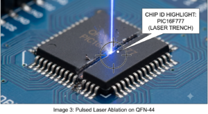
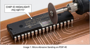
Extracting functional machine instructions from a secured, protected, or locked semiconductor requires an intricate understanding of physical microelectronic defenses. When specialists attempt to extract, recover, or restore system logic from an encrypted silicon layout, their main goal is to isolate the raw binary or heximal file stored deep within the internal hardware registers. This delicate procedure is carefully executed to dump both the primary flash program memory and the auxiliary eeprom cells, which together form the complete data archive of the machine.
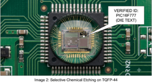
Successfully isolating this embedded instruction set enables technicians to rebuild system behavior and analyze functional software dependencies without requiring access to the original source code. Because the native microprocessor deploys internal security bits to block standard debug interfaces, obtaining a clean dump requires specialized low-level techniques to bypass the read bans without triggering a catastrophic erasure of the underlying firmware.
Disable the PWM pin (CCP1) output driver by setting the associated TRIS bit.
Set the PWM period by loading the PR2 register.
Configure the CCP module for the PWM mode by loading the CCP1CON register with the appropriate values.
Set the PWM duty cycle by loading the CCPR1L register and DC1B<1:0> bits of the CCP1CON register.
Configure and start Timer2:
- Clear the TMR2IF interrupt flag bit of the PIR1 register.
- Set the Timer2 prescale value by loading the T2CKPS bits of the T2CON register.
- Enable Timer2 by setting the TMR2ON bit of the T2CON register.
Overcoming these internal hardware defenses presents severe technical challenges and demands extreme precision during execution. Factory security schemes on a secured chip utilize buried anti-tamper meshes, power-glitch detectors, and voltage monitoring circuits designed to permanently erase the internal flash and eeprom storage arrays if unexpected probing is identified. If an unauthorized tool introduces improper electrical tolerances or timing delays during an extraction attempt, the target microprocessor will instantly lock down or destroy its stored data archive.
Why do corporate clients take on these delicate risks to open or hack a protected microcontroller? The necessity arises because original component vendors routinely go out of business, discontinue legacy product lines, or refuse to release proprietary code, leaving critical commercial infrastructure completely stranded whenever a single chip experiences a hardware fault.
Ultimately, obtaining a pristine binary or heximal file through controlled reverse engineering delivers immense operational resilience and financial advantages to our clients. Having unrestricted access to the firmware archive gives maintenance departments the freedom to clone obsolete controllers onto modern circuit assemblies, patch hidden software bugs, and ensure seamless system interoperability across the plant.
This proactive technical capability changes an inaccessible, locked hardware barrier back into a fully transparent digital asset—drastically lowering operational overhead, eliminating vendor lock-in, and extending the service life of high-value industrial equipment for years to come.