Extract MCU AT89C5130A Code is the necessary step for MCU Program recovery, the status of microcontroller will normally reset to open one after decapsulate the part and dump the firmware out from its flash and eeprom memory;
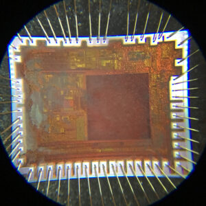
Extracting microcontroller AT89S53 code is a sophisticated process that combines knowledge of embedded systems, hardware hacking, and security exploitation. The AT89S53, developed by Atmel, is a powerful 8-bit microcontroller featuring 12K bytes of in-system programmable Flash memory, 256 bytes of RAM, and 32 I/O lines. It supports ISP (In-System Programming) and SPI (Serial Peripheral Interface) for programming and data transfer. However, once its memory is locked and secured, it becomes extremely difficult to access or recover the original firmware or source code.
Features
- 80C52X2 Core (6 Clocks per Instruction)
– Maximum Core Frequency 48 MHz in X1 Mode, 24 MHz in X2 Mode
– Dual Data Pointer
– Full-duplex Enhanced UART (EUART)
– Three 16-bit Timer/Counters: T0, T1 and T2
– 256 Bytes of Scratchpad RAM
16/32-Kbyte On-chip Flash EEPROM In-System Programming through USB
– Byte and Page (128 bytes) Erase and Write
– 100k Write Cycles
3-KbyteFlash EEPROM for Bootloader
– Byte and Page (128 bytes) Erase and Write
– 100k Write Cycles
1-Kbyte EEPROM Data (
– Byte and Page (128 bytes) Erase and Write
– 100k Write Cycles
On-chip Expanded RAM (ERAM): 1024 Bytes
Integrated Power Monitor (POR/PFD) to Supervise Internal Power Supply
USB 1.1 and 2.0 Full Speed Compliant Module with Interrupt on Transfer Completion
– Endpoint 0 for Control Transfers: 32-byte FIFO
– 6 Programmable Endpoints with In or Out Directions and with Bulk, Interrupt or
Isochronous Transfers
- Endpoint 1, 2, 3: 32-byte FIFO
- Endpoint 4, 5: 2 x 64-byte FIFO with Double Buffering (Ping-pong Mode)
- Endpoint 6: 2 x 512-byte FIFO with Double Buffering (Ping-pong Mode)
– Suspend/Resume Interrupts

– 48 MHz PLL for Full-speed Bus Operation
– Bus Disconnection on Microcontroller Request
5 Channels Programmable Counter Array (PCA) with 16-bit Counter, High-speed
Output, Compare/Capture, PWM and Watchdog Timer Capabilities when Extract Microcontroller code
Programmable Hardware Watchdog Timer (One-time Enabled with Reset-out): 100 ms to 3s at 8 MHz
Keyboard Interrupt Interface on Port P1 (8 Bits)
TWI (Two Wire Interface) 400Kbit/s
SPI Interface (Master/Slave Mode) 34 I/O Pins if Extract microcontroller at89s53 code
4 Direct-drive LED Outputs with Programmable Current Sources: 2-6-10 mA Typical
4-level Priority Interrupt System (11 sources)
Idle and Power-down Modes 0 to 24 MHz On-chip Oscillator with Analog PLL for 48 MHz Synthesis
Industrial Temperature Range
Extended Range Power Supply: 2.7V to 5.5V (3.3V to 5.5V required for USB)
Packages: PLCC52, VQFP64, QFN32
AT89C5130A/31A-M is a high-performance Flash version of the 80C51 single-chip 8-bit microcontrollers with full speed USB functions before Extract Microcontroller heximal.
AT89C5130A/31A-M features a full-speed USB module compatible with the USB specifications Version 1.1 and 2.0. This module integrates the USB transceivers with a 3.3V voltage regulator and the Serial Interface Engine (SIE) with Digital Phase Locked Loop and 48 MHz clock recovery.
USB Event detection logic (Reset and Suspend/Resume) and FIFO buffers supporting the mandatory control Endpoint (EP0) and up to 6 versatile Endpoints before Extract MCU (EP1/EP2/EP3/EP4/EP5/EP6) with minimum software overhead are also part of the USB module.
AT89C5130A/31A-M retains the features of the Atmel 80C52 with extended Flash capacity (16/32-Kbytes), 256 bytes of internal RAM, a 4-level interrupt system, two 16-bit timer/counters (T0/T1), a full duplex enhanced UART (EUART) and an on-chip oscillator.
In addition, AT89C5130A/31A-M has an on-chip expanded RAM of 1024 bytes (ERAM), a dual data pointer, a 16-bit up/down Timer (T2), a Programmable Counter Array (PCA), up to 4 programmable LED current sources, a programmable hardware watchdog and a power-on reset.
AT89C5130A/31A-M has two software-selectable modes of reduced activity for further reduction in power consumption. In the idle mode the CPU is frozen while the timers, the serial ports and the interrupt system are still operating. In the power-down mode the RAM is saved, the peripheral clock is frozen, but the device has full wake-up capability through USB events or external interrupts.