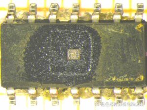
The PIC18F8525 microcontroller, manufactured by Microchip Technology, is a popular choice for embedded systems due to its robust performance and versatility. However, in some cases, engineers or developers may need to extract the source code from a secured PIC18F8525 MCU, either for recovery, analysis, or debugging purposes. This process involves bypassing the microcontroller’s security features, such as fuse bits, to read out the embedded firmware in binary or hexadecimal format.
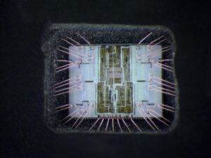
Microcontrollers like the PIC18F8525 are often programmed with security fuse bits enabled to protect intellectual property. These fuse bits prevent unauthorized access to the firmware stored in the MCU’s memory. However, with advanced techniques and specialized tools, it is possible to crack these security measures. Methods such as power glitching, UV light attacks, or using dedicated hardware programmers can be employed to bypass the fuse bits and extract the firmware.

Once the microprocessor PIC18F8525 security is bypassed, the firmware can be read out in binary or hexadecimal format using a programmer or debugger. This extracted data of Microchip PIC18F8525 microcomputer can then be disassembled or decompiled to reconstruct the original source code. It is important to note that such activities should only be performed for legitimate purposes, such as recovering lost code or debugging, and must comply with legal and ethical standards.
In conclusion, while extracting source code from a secured PIC18F8525 MCU is technically challenging, it is achievable with the right tools and expertise. Always ensure that such actions are conducted within legal boundaries and respect intellectual property rights.
We can Extract MCU PIC18F8525 Source Code, please view the MCU PIC18F8525 features for your reference:
Counter mode is selected by setting the T0CS bit. In Counter mode, Timer0 will increment, either on every rising or falling edge of pin RA4/T0CKI/AN2/VREF+. The incrementing edge is determined by the Timer0 Source Edge Select bit (T0SE). Clearing the T0SE bit selects the rising edge.
When an external clock input is used for Timer0, it must meet certain requirements. The requirements ensure the external clock can be synchronized with the internal phase clock (TOSC) when Copy Locked PIC16C65B Program. Also, there is a delay in the actual incrementing of Timer0 after synchronization.
An 8-bit counter is available as a prescaler for the Timer0 module. The prescaler is not readable or writable. The PSA and T0PS2:T0PS0 bits determine the prescaler assignment and prescale ratio. Clearing bit PSA will assign the prescaler to the Timer0 module. When the prescaler is assigned to the Timer0 module, prescale values of 1:2, 1:4, …, 1:256 are selectable.
When assigned to the Timer0 module, all instructions writing to the TMR0 register (e.g.,CLRF TMR0,MOVWF TMR0, BSF TMR0, x…, etc.) will clear the prescaler count only. The prescaler assignment is fully under software
control (i.e., it can be changed “on-the-fly” during program execution) if Extract MCU PIC18F8525 Source Code.
The TMR0 interrupt is generated when the TMR0 register overflows from FFh to 00h in 8-bit mode, or FFFFh to 0000h in 16-bit mode. This overflow sets the TMR0IF bit. The interrupt can be masked by clearing the TMR0IE bit by Extract Microcontroller PIC16C62B Code. The TMR0IF bit must be cleared in software by the Timer0 module Interrupt Service Routine before re-enabling this interrupt.
The TMR0 interrupt cannot awaken the processor from Sleep mode, since the timer requires clock cycles even when T0CS is set by Crack MCU.