Extract MCU PIC12C508 Firmware is centered on the recovery of embedded program data from a secured and permanently programmed microcontroller when no external archive or source code is available. As an OTP-based chip, the PIC12C508 stores its firmware in a non-rewritable memory structure, meaning the binary or heximal file exists only inside the device once deployed. When a system requires maintenance, duplication, or migration, engineers must rely on reverse engineering to open restricted access paths, extract a reliable memory dump, and restore the firmware archive into a usable format. The process focuses on reconstructing a consistent program file while preserving the integrity of the data stored within the microprocessor.
The recommendations of the maximum receiver baud rate error was made under the assumption that the Receiver and Transmitter equally divides the maximum total error. There are two possible sources for the receivers baud rate error. The Receiver’s system clock (XTAL) will always have some minor instability over the supply voltage range and the temperature range. When using a crystal to generate the system clock, this is rarely a problem, but for a resonator the system clock may differ more than 2% depending of the resonators tolerance.
The second source for the error is more controllable. The baud rate generator can not always do an exact division of the system frequency to get the baud rate wanted. In this case an UBRR value that gives an acceptable low error can be used if possible. Setting the Multi-processor Communication mode (MPCMn) bit in UCSRnA enables a filtering function of incoming frames received by the USART Receiver. Frames that do not contain address information will be ignored and not put into the receive buffer. This effectively reduces the number of incoming frames that has to be handled by the CPU, in a system with multiple MCUs that communicate via the same serial bus.
The Transmitter is unaffected by the MPCMn setting, but has to be used differently when it is a part of a system utilizing the Multi-processor Communication mode. If the Receiver is set up to receive frames that contain 5 to 8 data bits, then the first stop bit indicates if the frame contains data or address information. If the Receiver is set up for frames with nine data bits, then the ninth bit (RXB8n) is used for identifying address and data frames. When the frame type bit (the first stop or the ninth bit) is one, the frame contains an address. When the frame type bit is zero the frame is a data frame.
The Multi-processor Communication mode enables several slave MCUs to receive data from a master MCU. This is done by first decoding an address frame to find out which MCU has been addressed. If a particular slave MCU has been addressed, it will receive the following data frames as normal, while the other slave MCUs will ignore the received frames until another address frame is received.
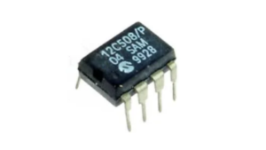
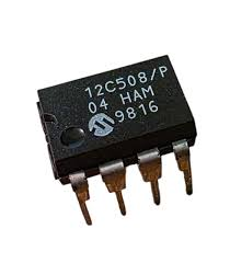
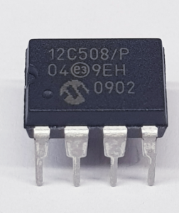
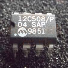
The PIC12C508 is a minimalist 8-bit microcontroller designed for ultra-compact and cost-sensitive applications. It integrates a small program memory space, internal oscillator, and basic I/O control, making it suitable for simple logic execution and timing-based operations. Despite its limited resources, the chip has been extensively deployed in consumer electronics, small household devices, remote transmitters, power control modules, and entry-level industrial controllers. In these systems, the firmware embedded in the chip functions as a fixed data archive, controlling all operational behavior of the device. The absence of EEPROM or modern flash flexibility reinforces the importance of preserving the program memory when dealing with legacy hardware.
Extract MCU PIC12C508 Firmware operations often require engineers to hack into a locked and protected MCU in order to extract, recover, restore, and reverse engineer the firmware stored in its internal memory. Because the chip is secured and designed to prevent direct readout, accessing the binary dump involves overcoming protection mechanisms while maintaining data consistency. The process must carefully handle the extraction of program memory, reconstruct the heximal file structure, and ensure that the firmware archive remains complete and accurate. Challenges include dealing with the rigid OTP architecture, limited memory mapping, and potential instability when attempting to open the chip for data retrieval. These constraints make the recovery process highly specialized and dependent on precise technical control.
The ability to recover firmware from a PIC12C508 microcontroller delivers tangible benefits for clients working with legacy embedded systems. By restoring a usable binary or program file, businesses can replicate existing MCU configurations, repair obsolete equipment, and extend the operational life of their products. The recovered firmware archive also supports reverse engineering analysis, enabling engineers to understand system logic, verify performance, and recreate missing source code when required. This reduces redevelopment costs, shortens downtime, and ensures continuity in production environments. Ultimately, Extract MCU PIC12C508 Firmware transforms a secured and inaccessible chip into a recoverable engineering resource, preserving valuable data and supporting long-term system sustainability.