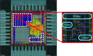
Extract Microcontroller PIC16F1903 Embedded Firmware
This technique compares device clock speed to some reference clock. Two timers may be used to faciliate the process of Extract Microcontroller PIC16F1903 Embedded Firmware;

This technique compares device clock speed to some reference clock. Two timers may be used to faciliate the process of Extract Microcontroller PIC16F1903 Embedded Firmware;

In Multi-Master mode, the interrupt generation on the detection of the Start and Stop conditions, allows the determination of when the bus is free when Read Out
The 4x frequency multiplier can be used with the internal oscillator block to produce faster device clock speeds than are normally possible with an internal
An SSP interrupt is generated for each data transferbyte. Flag bit SSPIF must be cleared in software, and the SSPSTAT register is used to determine the
Using the internal oscillator as the clock source eliminates the need for up to two external oscillator pins, which can then be used for digital
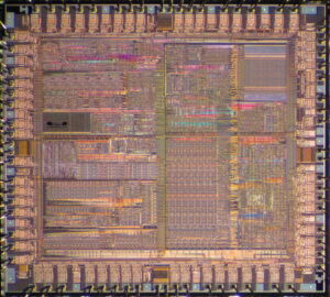
We can proceed with Secured Microcomputer PIC16F1828 Code Extraction, please view the Microcomputer PIC16F1828 features for your reference: A Phase Locked Loop (PLL) circuit is provided as
The sequence of events for 10-bit address is as follows, with steps 7-9 for slave-transmitter: Receive first (high) byte of address (bits SSPIF, BF and bit UA (SSPSTAT<1>)
In Slave mode, the SCL and SDA pins must be configured as inputs (TRISC<7:6> set). The SSP module will override the input state with the output