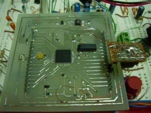
Readout Microchip PIC24FJ64GP205 Flash Heximal after unlock secured MCU PIC24FJ64GP205 fuse bit, and decrypt embedded program from pic24fj64gp205 microcontroller;
Real-Time Clock and Calendar (RTCC): This module implements a full-featured clock and calendar with alarm functions in hardware, freeing up timer resources and program memory space for use of the core. Deadman Timer (DMT): This module is provided to interrupt the processor in the event of a software.
Devices in the PIC24FJ64GP205 family are available in 28-pin, 36-pin and 48-pin packages. The general block diagram for all devices is shown in Figure 1-1 . A list of the pin features available on the PIC24FJ64GP205 family devices, sorted by function when readout microchip pic64fj32gp203 controller firmware, is shown in Table 1-1 when . Pin feature information is provided in the pinout diagrams in the beginning of this data sheet. Multiplexed features are sorted by the priority given to a feature, with the highest priority peripheral being listed first.
Not all I/O pins or features are implemented on all device pinout See pinout diagrams and tables for specific implementations by pin count.
BOR functionality is provided when the on-board voltage regulator is Some peripheral I/Os are only accessible through remappable
USB is available on PIC24FJXXXGUXXX devices
Getting started with the PIC24FJ64GP205/GU205 family of 16-bit microcontrollers requires attention to a minimal set of device pin connections before proceeding with development to copy microchip pic24fj32gp205 controller flash data.
The following pins must always be connected:
- All VDD, VUSB3V3 and VSS pins (see 2 Power Supply Pins)
- All AVDD and AVSS pins, regardless of whether or not the analog device features are used (see 2 Power Supply Pins)
- MCLR pin (see 3 Master Clear (MCLR) Pin)
- VCAP pin
(see 2.4 Voltage Regulator Pin (VCAP))
These pins must also be connected if they are being used in the end application:
PGECx/PGEDx pins used for In-Circuit Serial Programming™ (ICSP™) and debugging purposes (see 5 ICSP Pins)
OSCI and OSCO pins when an external oscillator is used (see 2.6 External Oscillator Pins)