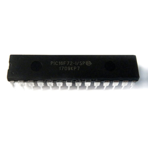
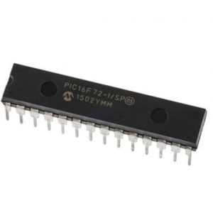
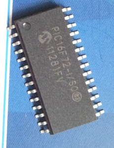
The microcontroller landscape is dominated by versatile components like the PIC16F72, a high-performance MCU from Microchip’s 8-bit family. This microprocessor is widely deployed across various sectors, including automotive electronics, industrial control systems, and consumer appliances, due to its integrated ADC, robust flashmemory, and efficient EEPROM storage. However, as products age or original manufacturers disappear, the need to Read MCU PIC16F72 Heximal data becomes a critical necessity for legacy support. These chips are often locked or protected by internal security bits designed to prevent unauthorized access to the programmemory. When a device is secured, the hardware inhibits standard programming interfaces from reading the binaryfile, effectively turning the chip into a black box to safeguard the intellectual property contained within its dataarchive.
Почему организации стремятся к реверс-инжинирингу и восстановлению шестнадцатеричного двоичного кода из защищенного микроконтроллера Microchip PIC16F72? Основной мотивацией часто является сохранение истории промышленности или поддержание критически важной инфраструктуры. Когда исходный код утерян из-за повреждения данных или ликвидации компании, единственный способ восстановить систему — это извлечь прошивку из существующего, работающего микроконтроллера Microchip PIC16F72. Вскрыв или взломав заблокированную флэш-память, инженеры могут выгрузить программу и создать резервную копию. Это позволяет восстановить важную логику, что дает возможность ремонтировать устаревшее оборудование или переносить программное обеспечение на более современные платформы Microchip PIC16F72. Без возможности чтения шестнадцатеричного файла из защищенного микроконтроллера Microchip PIC16F72 многие ценные промышленные активы превратились бы в электронные отходы просто из-за отсутствия двоичного архива. В конечном итоге, возможность чтения шестнадцатеричных данных с микроконтроллера MCU PIC16F72 предоставляет клиентам огромные конкурентные и функциональные преимущества. Успешное извлечение прошивки позволяет клиентам восстанавливать производственные линии, проводить аудит безопасности зашифрованных устройств или восстанавливать потерянную логику для обновления продуктов. Независимо от цели — будь то вскрытие заблокированного микропроцессора Microchip PIC16F72 для обеспечения резервирования или обратное проектирование двоичного файла для тестирования совместимости — результат один и тот же: освобождение программы из аппаратной оболочки. Преобразуя защищенный микроконтроллер Microchip PIC16F72 обратно в читаемый шестнадцатеричный архив, предприятия получают возможность оперативно поддерживать, клонировать или улучшать свои электронные активы, будучи полностью уверенными в целостности своих технических данных.
Tại sao các tổ chức lại tìm cách đảo ngược kỹ thuật và khôi phục mã nhị phân thập lục phân từ vi điều khiển Microchip PIC16F72 được bảo mật? Động lực chính thường là bảo tồn lịch sử công nghiệp hoặc duy trì cơ sở hạ tầng quan trọng. Khi mã nguồn gốc bị mất do lỗi dữ liệu hoặc công ty giải thể, cách duy nhất để khôi phục hệ thống là trích xuất phần mềm từ vi điều khiển Microchip PIC16F72 hiện có và đang hoạt động. Bằng cách chọn mở hoặc hack bộ nhớ flash bị khóa, các kỹ sư có thể trích xuất chương trình và tạo bản sao lưu. Điều này cho phép khôi phục logic thiết yếu, cho phép sửa chữa máy móc lỗi thời hoặc chuyển đổi phần mềm sang các nền tảng vi điều khiển Microchip PIC16F72 hiện đại hơn. Nếu không có khả năng đọc tệp thập lục phân từ vi điều khiển Microchip PIC16F72 được bảo vệ, nhiều tài sản công nghiệp có giá trị cao sẽ trở thành rác thải điện tử chỉ đơn giản vì thiếu kho lưu trữ nhị phân. Cuối cùng, khả năng đọc dữ liệu thập lục phân của MCU PIC16F72 mang lại lợi ích cạnh tranh và chức năng to lớn cho khách hàng. Bằng cách thực hiện trích xuất phần mềm thành công, khách hàng có thể khôi phục dây chuyền sản xuất, thực hiện kiểm tra bảo mật trên các thiết bị được mã hóa hoặc khôi phục logic bị mất để cập nhật sản phẩm. Cho dù mục tiêu là mở khóa vi xử lý Microchip PIC16F72 để sao lưu dự phòng hay phân tích ngược một tập tin nhị phân để kiểm tra khả năng tương thích, kết quả đều như nhau: giải phóng chương trình khỏi “lồng phần cứng” của nó. Bằng cách chuyển đổi vi điều khiển Microchip PIC16F72 được bảo mật trở lại thành một kho lưu trữ thập lục phân có thể đọc được, các doanh nghiệp có được sự linh hoạt để duy trì, sao chép hoặc cải thiện tài sản điện tử của họ với sự tự tin tuyệt đối về tính toàn vẹn dữ liệu kỹ thuật.
For the PIC16F72, bits <7:2>, CAL5- CAL0 are used for calibration. Adjusting CAL5-0 from 000000 to 111111 yields a higher clock speed. Note that bits 1 and 0 of OSCCAL are unimplemented and should be written as 0 when modifying OSCCAL for compatibility with future devices. For the PIC16F72, the upper 4 bits of the register are used. Writing a larger value in this location yields a higher clock speed. This configuration bit when unprogrammed (left in the ‘1’ state) enables the external MCLR function. When programmed, the MCLR function is tied to the internal VDD, and the pin is assigned to be a GPIO.
See Figure 8-7. When pin GP3/MCLR/VPP is configured as MCLR, the internal pull-up is always on.The PIC12C5XX family incorporates on-chip Power On Reset (POR) circuitry which provides an internal chip reset for most power-up situations. The on-chip POR circuit holds the chip in reset until VDD has reached a high enough level for proper operation. To take advantage of the internal POR, program the GP3/MCLR/VPP pin as MCLR and tie through a resistor to VDD or program the pin as GP3.
왜 기업들은 보안이 강화된 마이크로칩 PIC16F72 MCU에서 16진수 바이너리 데이터를 역설계하고 복구하려고 할까요? 주된 이유는 산업 역사 보존이나 중요 인프라 유지 관리입니다. 데이터 손상이나 회사 해산으로 인해 원본 소스 코드가 손실된 경우, 시스템을 복구하는 유일한 방법은 작동 중인 기존 마이크로칩 PIC16F72 마이크로컨트롤러에서 펌웨어를 추출하는 것입니다. 잠긴 플래시 메모리를 열거나 해킹하여 프로그램을 덤프하고 백업 아카이브를 생성할 수 있습니다. 이를 통해 핵심 로직을 복구하고, 노후된 장비를 수리하거나 소프트웨어를 최신 마이크로칩 PIC16F72 MCU 플랫폼으로 마이그레이션할 수 있습니다. 보호된 마이크로칩 PIC16F72 마이크로컨트롤러에서 16진수 파일을 읽을 수 없다면, 바이너리 아카이브가 없다는 이유만으로 많은 고가의 산업 자산이 폐기물로 전락할 수 있습니다. 궁극적으로, MCU PIC16F72의 16진수 데이터를 읽을 수 있는 능력은 고객에게 엄청난 경쟁력과 기능적 이점을 제공합니다. 펌웨어 추출에 성공하면 고객은 생산 라인을 복원하고, 암호화된 장치에 대한 보안 감사를 수행하거나, 제품 업데이트를 위해 손실된 로직을 복구할 수 있습니다. 잠금 해제를 위해 Microchip PIC16F72 마이크로프로세서를 열거나 호환성 테스트를 위해 바이너리 파일을 리버스 엔지니어링하는 등 어떤 목적이든 결과는 동일합니다. 바로 하드웨어에 갇힌 프로그램을 해방하는 것입니다. 보안이 강화된 Microchip PIC16F72 MCU를 읽기 가능한 16진수 아카이브로 변환함으로써 기업은 기술 데이터의 무결성을 완벽하게 보장하면서 전자 자산을 유지, 복제 또는 개선할 수 있는 유연성을 확보할 수 있습니다.
An internal weak pull-up resistor is implemented using a transistor. Refer to Table 11-1 for the pull-up resistor ranges. This will eliminate external RC components usually needed to create a Power-on Reset. A maximum rise time for VDD is specified. See Electrical Specifications for details. When the device starts normal operation (exits the reset condition), device operating parameters (voltage, frequency, temperature, …) must be met to ensure operation. If these conditions are not met, the device must be held in reset until the operating parameters are met.
Why do organizations seek to reverse engineering and recover the heximalbinary from a securedchip? The primary motivation is often the preservation of industrial history or the maintenance of critical infrastructure. When the original source code is lost due to data corruption or company dissolution, the only way to restore a system is to extract the firmware from an existing, working microcontroller. By choosing to open or hack the lockedflashmemory, engineers can dump the program and create a backup archive. This allows for the recovery of essential logic, enabling the repair of obsolete machinery or the migration of software to more modern MCU platforms. Without the ability to read the heximalfile from a protectedmicrocontroller, many high-value industrial assets would become e-waste simply because of a missing binaryarchive.
ऑर्गनाइज़ेशन एक सिक्योर्ड माइक्रोचिप PIC16F72 MCU से रिवर्स इंजीनियरिंग और हेक्सिमल बाइनरी को रिकवर क्यों करना चाहते हैं? इसका मुख्य मकसद अक्सर इंडस्ट्रियल हिस्ट्री को बचाना या ज़रूरी इंफ्रास्ट्रक्चर का मेंटेनेंस होता है। जब डेटा करप्शन या कंपनी के बंद होने की वजह से ओरिजिनल सोर्स कोड खो जाता है, तो सिस्टम को रिस्टोर करने का एकमात्र तरीका मौजूदा, काम कर रहे माइक्रोचिप PIC16F72 माइक्रोकंट्रोलर से फर्मवेयर निकालना है। लॉक की गई फ्लैश मेमोरी को खोलकर या हैक करके, इंजीनियर प्रोग्राम को डंप कर सकते हैं और एक बैकअप आर्काइव बना सकते हैं। इससे ज़रूरी लॉजिक की रिकवरी होती है, जिससे पुरानी मशीनरी की मरम्मत या सॉफ्टवेयर को ज़्यादा मॉडर्न माइक्रोचिप PIC16F72 MCU प्लेटफॉर्म पर माइग्रेट करना मुमकिन होता है। एक प्रोटेक्टेड माइक्रोचिप PIC16F72 माइक्रोकंट्रोलर से हेक्सिमल फ़ाइल को पढ़ने की क्षमता के बिना, कई हाई-वैल्यू इंडस्ट्रियल एसेट्स सिर्फ़ एक गायब बाइनरी आर्काइव की वजह से ई-वेस्ट बन जाएंगे। आखिर में, MCU PIC16F72 हेक्सिमल डेटा को पढ़ने की क्षमता क्लाइंट्स को बहुत ज़्यादा कॉम्पिटिटिव और फंक्शनल फायदे देती है। एक सफल फर्मवेयर एक्सट्रैक्ट करके, क्लाइंट प्रोडक्शन लाइन को रिस्टोर कर सकते हैं, एन्क्रिप्टेड डिवाइस पर सिक्योरिटी ऑडिट कर सकते हैं, या प्रोडक्ट अपडेट के लिए खोए हुए लॉजिक को रिकवर कर सकते हैं। चाहे मकसद रिडंडेंसी के लिए लॉक किए गए माइक्रोचिप PIC16F72 माइक्रोप्रोसेसर को खोलना हो या कम्पैटिबिलिटी टेस्टिंग के लिए बाइनरी फ़ाइल को रिवर्स इंजीनियरिंग करना हो, नतीजा एक ही है: प्रोग्राम को उसके हार्डवेयर केज से आज़ाद करना। एक सुरक्षित माइक्रोचिप PIC16F72 MCU को वापस एक रीडेबल हेक्सिमल आर्काइव में बदलकर, बिज़नेस को अपने टेक्निकल डेटा इंटीग्रिटी पर पूरे भरोसे के साथ अपने इलेक्ट्रॉनिक एसेट्स को मेंटेन करने, क्लोन करने या बेहतर बनाने की फुर्ती मिलती है।
Mengapa organisasi berupaya melakukan rekayasa balik dan memulihkan biner heksadesimal dari mikrokontroler Microchip PIC16F72 yang terlindungi? Motivasi utamanya seringkali adalah pelestarian sejarah industri atau pemeliharaan infrastruktur penting. Ketika kode sumber asli hilang karena kerusakan data atau pembubaran perusahaan, satu-satunya cara untuk memulihkan sistem adalah dengan mengekstrak firmware dari mikrokontroler Microchip PIC16F72 yang masih berfungsi. Dengan memilih untuk membuka atau meretas memori flash yang terkunci, para insinyur dapat membuang program dan membuat arsip cadangan. Hal ini memungkinkan pemulihan logika penting, memungkinkan perbaikan mesin yang sudah usang atau migrasi perangkat lunak ke platform mikrokontroler Microchip PIC16F72 yang lebih modern. Tanpa kemampuan untuk membaca file heksadesimal dari mikrokontroler Microchip PIC16F72 yang terlindungi, banyak aset industri bernilai tinggi akan menjadi limbah elektronik hanya karena arsip biner yang hilang. Pada akhirnya, kemampuan untuk membaca data heksadesimal MCU PIC16F72 memberikan manfaat kompetitif dan fungsional yang sangat besar bagi klien. Dengan melakukan ekstraksi firmware yang sukses, klien dapat memulihkan jalur produksi, melakukan audit keamanan pada perangkat terenkripsi, atau memulihkan logika yang hilang untuk pembaruan produk. Baik tujuannya untuk membuka mikroprosesor Microchip PIC16F72 yang terkunci untuk redundansi atau untuk merekayasa balik file biner untuk pengujian kompatibilitas, hasilnya sama: pembebasan program dari sangkar perangkat kerasnya. Dengan mengubah MCU Microchip PIC16F72 yang diamankan kembali menjadi arsip heksadesimal yang dapat dibaca, bisnis mendapatkan kelincahan untuk memelihara, mengkloning, atau meningkatkan aset elektronik mereka dengan keyakinan penuh pada integritas data teknisnya.