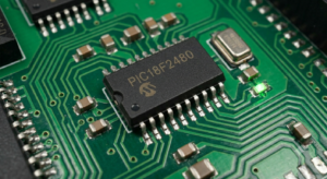
In the complex domain of automotive and industrial control systems, the longevity of legacy hardware is often a precarious balance. When engineering teams are faced with critical infrastructure failures, the specialized technique of protected mcu pic18f2480 code reading emerges as a necessary solution to preserve institutional knowledge. The pic18f2480 is a robust 8-bit microcontroller featuring an integrated ecanc™ controller, high-speed performance, and extensive power management capabilities, making it a cornerstone component for automotive engine control units (ecus), industrial fieldbus gateways, and sophisticated robotics controllers. As these systems reach their end-of-service life, companies often discover that their original technical files have been misplaced, leaving them with no way to maintain or replace faulty hardware. By turning to systematic digital forensics, firms can prevent the sudden obsolescence of essential machinery, ensuring that their proprietary operational workflows continue uninterrupted regardless of original vendor availability.
The Internal Oscillator Frequency Select bits (IRCF2:IRCF0) select the frequency output of the internal oscillator block to drive the device clock. The choices are the INTRC source, the INTOSC source (8 MHz) or one of the frequencies derived from the INTOSC postscaler (31.25 kHz to 4 MHz).
If the internal oscillator block is supplying the device clock,changing the states of these bits will have an immediate change on the internal oscillator’s output. On device Resets, the default output frequency of the internal oscillator block is set at 1 MHz.
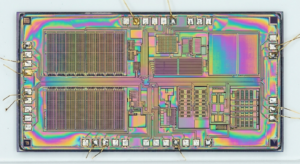
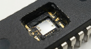
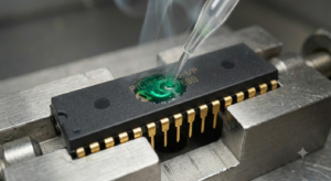
To extract internal logic from a secured or locked device, engineers must engage in a high-stakes reverse engineering process that demands precise technical control. The main hurdle when you attempt to hack into an encrypted chip is navigating the hardware-based security fuses designed to block all external debugging tools. The microcontroller utilizes sophisticated internal defenses to monitor for any unauthorized electrical probing, often triggering a destructive wipe of the flash and eeprom storage if the system detects an anomaly. If the program is not handled with extreme care, the microprocessor will instantly destroy the data archive, leaving the dump empty and useless. Successfully circumventing these protected mechanisms allows our teams to open the internal memory blocks and capture the raw binary instructions. This critical archive contains the complete heximal file strings required to restore and replicate the original system firmware.
When we recover this vital information, the primary objective is to recreate a stable operational environment from the captured data file without needing the original source code. The act of breaking off the locked status of an mcu is not merely a technical exercise; it is a strategic business maneuver. Many organizations rely on discontinued hardware that performs essential tasks, and the inability to replace or support these components can lead to costly, multi-year migration projects. By extracting the binary dump, we enable our clients to clone these units, implement necessary security patches, and bridge the gap between legacy environments and modern systems. Transforming a secured and inaccessible chip back into a functional, documented software archive provides the ultimate assurance that critical investments in automated infrastructure are shielded from the unexpected failure of long-retired silicon components.
When a nominal output frequency of 31 kHz is selected (IRCF2:IRCF0 = 000), users may choose which internal oscillator acts as the source. This is done with the INTSRC bit in the OSCTUNE register (OSCTUNE<7>). Setting this bit selects INTOSC as a 31.25 kHz clock source by enabling the divide-by-256 output of the INTOSC postscaler. Clearing INTSRC selects INTRC (nominally 31 kHz) as the clock source.
This option allows users to select the tunable and more precise INTOSC as a clock source, while maintaining power savings with a very low clock speed. Regardless of the setting of INTSRC, INTRC always remains the clock source for features such as the Watchdog Timer and the Fail-Safe Clock Monitor.
The OSTS, IOFS and T1RUN bits indicate which clock source is currently providing the device clock. The OSTS bit indicates that the Oscillator Start-up Timer has timed out and the primary clock is providing the device clock in primary clock modes. The IOFS bit indicates when the internal oscillator block has stabilized and is providing the device clock in RC Clock modes.
The T1RUN bit (T1CON<6>) indicates when the Timer1 oscillator is providing the device clock in secondary clock modes. In power managed modes, only one of these three bits will be set at any time. If none of these bits are set, the INTRC is providing the clock or the internal oscillator block has just started and is not yet stable.
Microchip PIC18F2480 마이크로컨트롤러는 비인가 전기적 탐지를 감시하기 위한 정교한 내부 보호 메커니즘을 사용하며, 이상 상황이 감지될 경우 플래시 메모리와 EEPROM 저장 영역의 삭제 절차를 활성화할 수 있습니다. 만약 Microchip PIC18F2480 MCU의 프로그램이 극도로 신중하게 처리되지 않으면, 마이크로프로세서는 즉시 데이터 아카이브를 삭제하여 확보된 덤프를 사용할 수 없게 만듭니다.
이러한 보호 메커니즘을 성공적으로 우회하면 엔지니어링 팀은 내부 메모리 블록에 접근하여 원시 바이너리 명령어를 확보할 수 있습니다. 이 핵심 데이터 아카이브에는 원본 Microchip PIC18F2480 마이크로프로세서 펌웨어를 복구하고 재현하는 데 필요한 전체 HEX 파일 데이터가 포함되어 있습니다.
The broader implications of this work center on providing our partners with genuine technological sovereignty. Having a verified digital archive of the system firmware grants businesses the autonomy to manage their assets as they see fit, rather than being bound by the changing support policies of original component suppliers. By mastering the ability to safely restore and analyze these hidden program sets, we assist our clients in mitigating supply chain risks, optimizing equipment performance, and extending the operational lifespan of their core technologies. This approach effectively converts an opaque, protected hardware unit into a transparent, manageable software asset, ensuring that the critical data residing within your industrial microcontroller remains a permanent, usable resource that supports your long-term production and reliability goals.