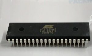
How to Extract Microcontroller AT89C55WD EEPROM: Breaking Secured Firmware Protection
Extracting microcontroller AT89C55WD EEPROM is a complex process due to its secured and locked firmware protection. Engineers and security researchers often attempt to break, hack, or decrypt the memory to recover essential program data stored in the EEPROM, flash, or other memory regions of this microcontroller. The AT89C55WD, an enhanced version of the AT89C55, features additional protection mechanisms, making code extraction even more challenging.
Methods to Crack AT89C55WD EEPROM Protection
- Decapsulation Attack: One of the most invasive techniques involves decapsulating the microcontroller to expose internal circuits. This method allows direct access to the EEPROM and flash memory, potentially enabling a binary dump.
- EEPROM Dumping: Specialized tools and techniques can be used to dump the locked EEPROM contents. However, encrypted or protected firmware regions pose additional difficulties in decoding the extracted data.
- Fault Injection: By introducing voltage or clock glitches, attackers may be able to bypass secured memory protections and extract binary program files stored within the microcontroller.
- Reverse Engineering: If portions of the source code, firmware archive, or binary program are available, reverse engineering can help decode and replicate the microprocessor’s logic.
- Software Exploits: Some MCUs, including the AT89C55WD, may have software vulnerabilities that allow hackers to decrypt or copy firmware from protected memory.
Ethical and Legal Considerations
Attempting to extract, clone, or duplicate EEPROM contents from a locked microcontroller without authorization is illegal and unethical. It is crucial to ensure compliance with intellectual property laws when attempting to recover or replicate secured firmware.
Conclusion
Extracting microcontroller AT89C55WD EEPROM data requires advanced hacking techniques such as decapsulation, fault injection, or EEPROM dumping. Due to encryption and security enhancements, breaking or decrypting locked firmware remains a significant challenge. Always consider legal and ethical implications before attempting any form of MCU code extraction.
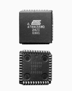
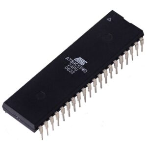
We can Extract Microcontroller AT89C55WD Eeprom, please view the Microcontroller AT89C55WD features for your reference:
The WDT is intended as a recovery method in situations where the CPU may be subjected to software upsets. The WDT consists of a 13-bit counter and the WatchDog Timer Reset (WDTRST) SFR. The WDT is defaulted to disable from exiting reset. To enable the WDT, a user must write 01EH and 0E1H in sequence to the WDTRST register (SFR location 0A6H). When the WDT is enabled, it will increment every machine cycle while the oscillator is running.
The WDT time-out period is dependent on the external clock frequency. There is no way to disable the WDT except through reset (either hardware reset or WDT overflow reset). When WDT overflows, it will drive an output RESET HIGH pulse at the RST pin. To enable the WDT, a user must write 01EH and 0E1H in sequence to the WDTRST register (SFR location 0A6H). When the WDT is enabled, the user needs to service it by writing 01EH and 0E1H to WDTRST to avoid a WDT overflow if Extract Microcontroller.
The 13-bit counter overflows when it reaches 8191 (1FFFH), and this will reset the device. When the WDT is enabled, it will increment every machine cycle while the oscillator is running. This means the user must reset the WDT at least every 8191 machine cycles. To reset the WDT the user must write 01EH and 0E1H to WDTRST. WDTRST is a write-only register. The WDT counter cannot be read or written before Extract Microcontroller.
When WDT overflows, it will generate an output RESET pulse at the RST pin. The RESET pulse duration is 98xTOSC, where TOSC=1/FOSC. To make the best use of the WDT, it should be serviced in those sections of code that will periodically be executed within the time required to prevent a WDT reset after Extract Microcontroller.
In Power-down mode the oscillator stops, which means the WDT also stops. While in Power-down mode, the user does not need to service the WDT. There are two methods of exiting Power-down mode: by a hardware reset or via a level-activated external interrupt which is enabled prior to entering Power-down mode. When Power-down is exited with hardware reset, servicing the WDT should occur as it normally does whenever the AT89C55WD is reset when Extract Microcontroller.
Exiting Power-down with an interrupt is significantly different. The interrupt is held low long enough for the oscillator to stabilize. When the interrupt is brought high, the interrupt is serviced. To prevent the WDT from resetting the device while the interrupt pin is held low, the WDT is not started until the interrupt is pulled high. It is suggested that the WDT be reset during the interrupt service for the interrupt used to exit Power-down if Extract Microcontroller.
To ensure that the WDT does not overflow within a few states of exiting Power-down, it is best to reset the WDT just before entering Power-down. Before going into the IDLE mode, the WDIDLE bit in SFR AUXR is used to determine whether the WDT continues to count if enabled. The WDT keeps counting during IDLE (WDIDLE bit = 0) as the default state. To prevent the WDT from resetting the AT89C55WD while in IDLE mode, the user should always set up a timer that will periodically exit IDLE, service the WDT, and reenter IDLE mode before Extract Microcontroller.
With WDIDLE bit enabled, the WDT will stop to count in IDLE mode and resumes the count upon exit from IDLE. The UART in the AT89C55WD operates the same way as the UART in the AT89C51 and AT89C52. For further information, see the December 1997 Microcontroller Data Book, page 2-48, section titled, “Serial Interface” after Extract Microcontroller.
Timer 0 and Timer 1 in the AT89C55WD operate the same way as Timer 0 and Timer 1 in the AT89C51 and AT89C52. Timer 2 is a 16-bit Timer/Counter that can operate as either a timer or an event counter. The type of operation is selected by bit C/T2 in the SFR T2CON (shown in Table 2). Timer 2 has three operating modes: capture, auto-reload (up or down counting), and baud rate generator if Extract Microcontroller.
The modes are selected by bits in T2CON, as shown in Table 2. Timer 2 consists of two 8-bit registers, TH2 and TL2. In the Timer function, the TL2 register is incremented every machine cycle. Since a machine cycle consists of 12 oscillator periods, the count rate is 1/12 of the oscillator frequency when Extract Microcontroller.
In the Counter function, the register is incremented in response to a 1-to-0 transition at its corresponding external input pin, T2. In this function, the external input is sampled during S5P2 of every machine cycle. When the samples show a high in one cycle and a low in the next cycle, the count is incremented. The new count value appears in the register during S3P1 of the cycle following the one in which the transition was detected.
Since two machine cycles (24 oscillator periods) are required to recognize a 1-to-0 transition, the maximum count rate is 1/24 of the oscillator frequency. To ensure that a given level is sampled at least once before it changes, the level should be held for at least one full machine cycle.