Extract MCU PIC12C508A Code represents a specialized engineering task focused on retrieving firmware from a secured and permanently programmed microcontroller. Unlike modern flash-based MCU devices, the PIC12C508A is built on OTP architecture, where the program memory becomes a fixed archive once written. When original source code, binary files, or project documentation are missing, the only remaining data resides inside the chip itself. In these cases, reverse engineering techniques are applied to open access to a locked device, extract a reliable memory dump, and recover a structured heximal or binary file. The objective is to restore the embedded firmware without altering its integrity, enabling future reuse or analysis of the program stored within the microprocessor.
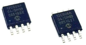
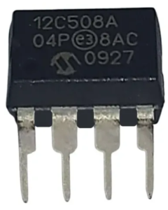
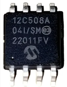
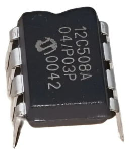
The PIC12C508A is a compact 8-bit microcontroller widely recognized for its simplicity, low cost, and minimal pin configuration. With limited program memory, basic GPIO functionality, and internal oscillator support, it is optimized for small embedded applications requiring straightforward control logic. This MCU has been broadly deployed in consumer electronics such as remote controls, small home appliances, LED drivers, power adapters, and security devices. It also appears in industrial environments where cost efficiency and stability are critical. In these applications, the firmware stored in the chip acts as a self-contained program archive, defining all operational behavior, timing sequences, and input/output responses within the system.
The clock recovery logic synchronizes internal clock to the incoming serial frames. Figure 87 illustrates the sampling process of the start bit of an incoming frame. The sample rate is 16 times the baud rate for Normal mode, and eight times the baud rate for Double Speed mode. The horizontal arrows illustrate the synchronization variation due to the sampling process. Note the larger time variation when using the Double Speed mode (U2Xn = 1) of operation. Samples denoted zero are samples done when the RxDn line is idle (i.e., no communication activity).
Please shown in the figure. The clock recovery logic then uses samples 8, 9, and 10 for Normal mode, and samples 4, 5, and 6 for Double Speed mode (indicated with sample numbers inside boxes on the figure), to decide if a valid start bit is received. If two or more of these three samples have logical high levels (the majority wins), the start bit is rejected as a noise spike and the Receiver starts looking for the next high to low-transition.
If however, a valid start bit is detected, the clock recovery logic is synchronized and the data recovery can begin. The synchronization process is repeated for each start bit. When the receiver clock is synchronized to the start bit, the data recovery can begin. The data recovery unit uses a state machine that has 16 states for each bit in Normal mode and eight states for each bit in Double Speed mode. Figure 88 shows the sampling of the data bits and the parity bit. Each of the samples is given a number that is equal to the state of the recovery unit.
The decision of the logic level of the received bit is taken by doing a majority voting of the logic value to the three samples in the center of the received bit. The center samples are emphasized on the figure by having the sample number inside boxes. The majority voting process is done as follows: If two or all three samples have high levels, the received bit is registered to be a logic 1. If two or all three samples have low levels, the received bit is registered to be a logic 0. This majority voting process acts as a low pass filter for the incoming signal on the RxDn pin. The recovery process is then repeated until a complete frame is received. Including the first stop bit. Note that the Receiver only uses the first stop bit of a frame.
Extract MCU PIC12C508A Code projects often involve complex scenarios where engineers must hack into a protected or locked chip to extract, recover, and restore firmware from internal program memory. Because the device is secured and lacks conventional EEPROM or flash reprogramming features, accessing the data requires careful reverse engineering strategies. The process must overcome read-protection mechanisms while preserving the integrity of the binary dump. Challenges include reconstructing a complete heximal file from constrained memory space, dealing with potential data fragmentation, and ensuring that the recovered firmware archive accurately reflects the original program. These operations are conducted in a controlled manner, focusing on reliable data extraction without exposing proprietary technical methods.
From a business and engineering perspective, the ability to recover firmware from a PIC12C508A microcontroller delivers substantial value. By restoring a usable binary or program file, clients can replicate legacy designs, repair discontinued products, and maintain long-term system compatibility. The recovered firmware archive enables deeper reverse engineering analysis, helping teams understand device behavior, validate system performance, and rebuild missing source code when necessary. This significantly reduces redevelopment costs and minimizes operational downtime. Ultimately, Extract MCU PIC12C508A Code services convert a secured and otherwise inaccessible chip into a reusable digital asset, ensuring continuity and sustainability for embedded systems across a wide range of industries.