To Extract MCU ATtiny44 Code is to undertake a focused and responsible effort to retrieve the compiled program image that resides in a small, resource-constrained microcontroller. The ATtiny44 is an AVR-class MCU valued for its efficient power profile, flexible I/O, and modest flash and EEPROM capacities—traits that make it ideal for compact designs such as battery-powered sensors, wearable controls, simple user interfaces, lighting drivers, and a range of consumer and industrial peripherals. In many products the flash holds not only machine code but calibration tables, device-specific settings and communication stacks that together define product behavior.
When teams need to recover a device’s program — for example after lost source repositories, failed updates, or to support long-lived legacy hardware — obtaining a clean binary or hex dump from the chip can be the only practical starting point. This is often referred to in practice as recovering, restoring or replicating embedded software, and the recovered binary archive becomes the basis for analysis, validation, or lawful reproduction. Because manufacturers frequently set protection bits or fuse settings to make on-chip memory read-protected, the task often requires careful reverse engineering and non-destructive handling, not brute force attempts to crack or hack devices.
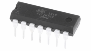
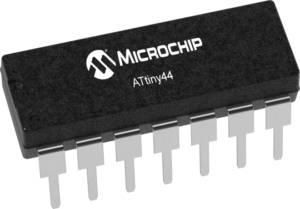
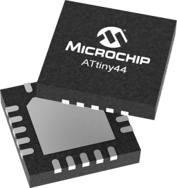
Extract MCU ATtiny44 Code from its flash memory, decipher the atmel avr chip attiny44 from its locked memory and recovery heximal file from microcontroller attiny44;
- EEPROM read from application code does not work in Lock Bit Mode 3
- Reading EEPROM when system clock frequency is below 900 kHz may not work;
- EEPROM read from application code does not work in Lock Bit Mode 3 When the Memory Lock Bits LB2 and LB1 are programmed to mode 3, EEPROM read does not work from the application code. Problem Fix/Work around Do not set Lock Bit Protection Mode 3 when the application code needs to read from EEPROM.
- Reading EEPROM when system clock frequency is below 900 kHz may not work Reading data from the EEPROM at system clock frequency below 900 kHz may result in wrong data read. Problem Fix/Work around Avoid using the EEPROM at clock frequency below 900 kHz.
- Reading EEPROM when system clock frequency is below 900 kHz may not work
- Reading EEPROM when system clock frequency is below 900 kHz may not work Reading data from the EEPROM at system clock frequency below 900 kHz may result in wrong data read.
Problem Fix/Work around Avoid using the EEPROM at clock frequency below 900 kHz.
The ATtiny44 offers analog and digital peripherals, timers, and serial interfaces that suit meters, small motor controllers, and user-interface modules. Its limited memory footprint encourages compact, optimized code: while efficient, this makes the resulting binary dense and sometimes harder to interpret. Extracting a dump from a protected device therefore usually yields a compact archive of machine instructions and data that must be decoded and analyzed by experienced engineers to reconstruct meaningful program flow or recover lost application logic.
Practical difficulties are both technical and procedural. Logical protections—set to prevent copying—mean ordinary programming tools may refuse readout. Physically, the small packages and crowded PCBs typical of ATtiny44 applications can hide debug pads or complicate access; attempting invasive access risks corrupting the EEPROM or destroying the chip and its stored data. Even with a successful dump, interpreting the file into useful source-level information requires careful study: symbol names, comments and high-level structure are absent in compiled code, so skilled reverse engineering is necessary to recreate intent without introducing errors.
Port A is a 8-bit bi-directional I/O port with internal pull-up resistors (selected for each bit). The Port A output buffers have symmetrical drive characteristics with both high sink and source capability. As inputs, Port A pins that are externally pulled low will source current if the pull-up resistors are activated by extracting microchip attiny44v mcu firmware. The Port A pins are tri-stated when a reset condition becomes active, even if the clock is not running.
Port A has an alternate functions as analog inputs for the ADC, analog comparator, timer/counter, SPI and pin change interrupt as described in ”Alternate Port Functions” on page 61.
Port B is a 4-bit bi-directional I/O port with internal pull-up resistors (selected for each bit). The Port B output buffers have symmetrical drive characteristics with both high sink and source capability except PB3 which has the RESET capability. To use pin PB3 as an I/O pin, instead of RESET pin, program (‘0’) RSTDISBL fuse. As inputs, Port B pins that are externally pulled low will source current if the pull-up resistors are activated. The Port B pins are tri-stated when a reset condition becomes active, even if the clock is not running.
Why perform this work? For clients the benefits are tangible. A verified firmware image reduces downtime by enabling field repairs and re-flashing, supports compliance by allowing safety and security audits of deployed code, and preserves corporate knowledge when original vendors stop support. In manufacturing or MRO contexts, lawful duplication or replication of firmware under proper authorization helps maintain spare-part inventories and extend product lifecycles. Importantly, these outcomes are achieved under clear legal authority and with documented provenance to avoid misuse.
Ethics and legality are central: describing technical possibilities using terms like break, attack or decrypt can suggest adversarial intent, so responsible providers emphasize authorization, documented scope, and non-destructive methods. The goal when you Extract MCU ATtiny44 Code is not to enable piracy but to recover, protect, and manage the software assets that keep devices safe and operational. Done correctly, the process returns a once-inaccessible program archive into a controlled, analyzable form that lets clients maintain, secure, and evolve their embedded systems.