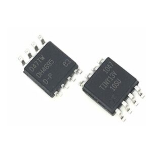
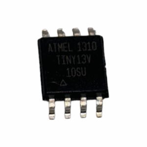
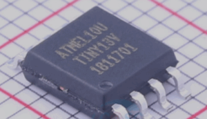
To extract MCU ATTINY13V heximal from a secured or protected microcontroller is a delicate and technically advanced process requiring deep understanding of microelectronic architecture and data recovery. The ATTINY13V, a compact 8-bit AVR microcontroller by Atmel (now Microchip), is widely used in low-power embedded applications such as remote controllers, battery-powered devices, and industrial sensors. It includes 1KB of in-system programmable flash memory, 64 bytes of EEPROM, and a 64-byte SRAM. While seemingly small in storage, this MCU often contains critical firmware code that developers seek to recover, copy, or reverse engineer.
However, Atmel embedded strong lock bit features to prevent unauthorized access, making the chip encrypted, locked, and resilient to simple readback attempts. Once code protection is enabled, any standard programmer is rendered useless in accessing the internal program data, leading to the need for non-standard approaches to dump or extract the binary or heximal code.
Extract MCU ATTINY13V Heximal from Microcontroller ATtiny13V to complete the crack MCU process by removing the protection over its flash and eeprom memory;
Wrong values read after Erase Only operation
At supply voltages below 2.7 V, an EEPROM location that is erased by the Erase Only operation may read as programmed (0x00).
Problem Fix/Workaround
If it is necessary to read an EEPROM location after Erase Only, use an Atomic Write operation with 0xFF as data in order to erase a location. In any case, the Write Only operation can be used as intended. Thus no special considerations are needed as long as the erased location is not read before it is programmed when read mcu at89c51rc2 bin.
High Voltage Serial Programming Flash, EEPROM, Fuse and Lock Bits may fail
Writing to any of these locations and bits may in some occasions fail.
Problem Fix/Workaround
After a writing has been initiated, always observe the RDY/BSY signal. If the writing should fail, rewrite until the RDY/BSY verifies a correct writing. This will be fixed in revision D.
Device may lock for further programming
Special combinations of fuse bits will lock the device for further programming effectively turning it into an OTP device. The following combinations of settings/fuse bits will cause this effect after Extract ic at89c5115 code:
128 kHz internal oscillator (CKSEL[1..0] = 11), shortest start-up time (SUT[1..0] = 00), Debugwire enabled (DWEN = 0) or Reset disabled RSTDISBL = 0.
9.6 MHz internal oscillator (CKSEL[1..0] = 10), shortest start-up time (SUT[1..0] = 00), Debugwire enabled (DWEN = 0) or Reset disabled RSTDISBL = 0.
4.8 MHz internal oscillator (CKSEL[1..0] = 01), shortest start-up time (SUT[1..0] = 00), Debugwire enabled (DWEN = 0) or Reset disabled RSTDISBL = 0 when Extract MCU at89c51cc01 code.
Problem fix/ Workaround
Avoid the above fuse combinations. Selecting longer start-up time will eliminate the problem.
DebugWIRE communication not blocked by lock-bits
When debugWIRE on-chip debug is enabled (DWEN = 0), the contents of program memory and EEPROM data memory can be read even if the lock-bits are set to block further reading of the device.
Problem fix/ Workaround
Do not ship products with on-chip debug of the tiny13 enabled.
Watchdog Timer Interrupt disabled
If the watchdog timer interrupt flag is not cleared before a new timeout occurs, the watchdog will be disabled, and the interrupt flag will automatically be cleared. This is only applicable in interrupt only mode. If the Watchdog is configured to reset the device in the watchdog time-out following an interrupt, the device works correctly.
Problem fix / Workaround
Make sure there is enough time to always service the first timeout event before a new watchdog timeout occurs. This is done by selecting a long enough time-out period.
EEPROM can not be written below 1.9 Volt
Writing the EEPROM at VCC below 1.9 volts might fail.
Problem Fix/Workaround
Do not write the EEPROM when VCC is below 1.9 volts.
To crack or hack a locked ATTINY13V, highly specialized procedures are employed. These include:
-
Decapsulation: The chip package is chemically or mechanically removed to expose the silicon die for microscopic analysis or fault injection.
-
Invasive memory probing: By applying conductive micro-needles or scanning electron microscopy (SEM), experts can potentially decode or read stored data at a physical level.
-
Glitch attacks: Brief fluctuations in power or clock timing may temporarily bypass security logic, enabling partial dump of the protected memory.
-
Laser fault injection: Precision laser pulses can be used to alter logic gates momentarily, effectively overriding security fuses.
Each method carries its own set of risks and costs, often requiring custom setups, cleanroom conditions, and extensive trial and error. Unlike higher-end MCUs, the ATTINY13V’s limited interface options (e.g., no JTAG) eliminate most traditional entry points, which raises the bar for reverse engineering. Even though its firmware archive is small, extracting this data can be just as complex as from much larger chips due to minimal hardware attack surface.
Once the binary or source code is successfully extracted, the result can be replicated, duplicated, or restored into another microprocessor, supporting legacy maintenance, competitive analysis, or firmware backups.
In summary, to extract MCU ATTINY13V heximal from a locked chip involves a serious, expert-driven attack on physical and logical protection layers. The effort to clone, recover, or decrypt its memory makes it a hallmark of modern microcontroller reverse engineering.