Extract IC PIC16C57C Code targets a niche but critical requirement: retrieving firmware from a secured, protected, or locked legacy MCU where no development backups exist. The PIC16C57C uses an OTP program memory model, so the firmware becomes a permanent archive inside the chip once programmed. When documentation is lost, reverse engineering is the only practical path to recover a usable binary or heximal file. In this context, engineers aim to open restricted access paths, extract a consistent memory dump, and restore the program structure into a coherent file suitable for validation and reuse. The emphasis is on data fidelity—ensuring the recovered firmware reflects the exact state of the microprocessor at deployment.
The Parity Checker is active when the high USART Parity mode (UPMn1) bit is set. Type of Parity Check to be performed (odd or even) is selected by the UPMn0 bit.
When enabled, the Parity Checker calculates the parity of the data bits in incoming frames and compares the result with the parity bit from the serial frame.
The result of the check is stored in the receive buffer together with the received data and stop bits. The Parity Error (UPEn) Flag can then be read by software to check if the frame had a Parity Error.
The UPEn bit is set if the next character that can be read from the receive buffer had a Parity Error when received and the Parity Checking was enabled at that point (UPMn1 = 1). This bit is valid until the receive buffer (UDRn) is read.
In contrast to the Transmitter, disabling of the Receiver will be immediate. Data from ongoing receptions will therefore be lost. When disabled (i.e., the RXENn is set to zero) the Receiver will no longer override the normal function of the RxDn port pin.
The Receiver buffer FIFO will be flushed when the Receiver is disabled. Remaining data in the buffer will be lost. The receiver buffer FIFO will be flushed when the Receiver is disabled, i.e., the buffer will be emptied of its contents.
Unread data will be lost. If the buffer has to be flushed during normal operation, due to for instance an error condition, read the UDRn I/O location until the RXCn Flag is cleared. The following code example shows how to flush the receive buffer.
The USART includes a clock recovery and a data recovery unit for handling asynchronous data reception. The clock recovery logic is used for synchronizing the internally generated baud rate clock to the incoming asynchronous serial frames at the RxDn pin.
The data recovery logic samples and low pass filters each incoming bit, thereby improving the noise immunity of the Receiver. The asynchronous reception operational range depends on the accuracy of the internal baud rate clock, the rate of the incoming frames, and the frame size in number of bits.
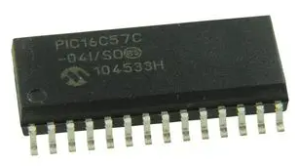
Architecturally, the PIC16C57C is a compact 8-bit microcontroller built on a Harvard design with separate program and data spaces. It provides sufficient I/O, timer functionality, and deterministic instruction execution for straightforward control tasks. Although it lacks modern flash reprogrammability and extensive EEPROM resources, it excels in stable, cost-effective deployments. The chip is commonly found in legacy consumer appliances, simple industrial controllers, alarm systems, automotive auxiliaries, and low-cost automation modules. In these products, the MCU executes a tightly optimized program stored in its internal memory, forming a self-contained firmware archive that governs timing, control flow, and device interaction.
Extract IC PIC16C57C Code engagements typically require engineers to hack around read restrictions in order to extract, recover, and restore firmware from secured program memory. A protected or locked device resists standard attempts to open its contents, and the OTP nature of the chip complicates any effort to duplicate or migrate the program. Reverse engineering must therefore be conducted with precision to obtain a reliable binary dump while preserving data integrity. Challenges include handling limited memory organization, dealing with potential protection features that inhibit readout, and reconstructing a valid heximal file from the retrieved data. The goal is to build a clean firmware archive that can be analyzed or re-targeted without introducing inconsistencies.
The practical value of extracting PIC16C57C code is substantial for organizations maintaining legacy platforms. By recovering firmware and restoring a functional program file, clients can replicate discontinued designs, service aging equipment, and extend product lifecycles without full redevelopment. Access to the recovered binary enables deeper analysis, supports troubleshooting, and can assist in recreating source code structures when needed. This reduces cost, minimizes downtime, and safeguards intellectual property embedded within the MCU. Ultimately, Extract IC PIC16C57C Code transforms an inaccessible, locked chip into a usable engineering asset, enabling continuity and long-term support for systems that would otherwise face obsolescence.