Extract Chip ATmega169PA Heximal refers to the professional process of retrieving firmware data from a secured ATmega169PA microcontroller when the internal program memory is no longer accessible through normal programming tools. In many embedded devices, the MCU stores its operating firmware in flash memory while EEPROM retains configuration parameters, calibration data, or system settings. Once a chip becomes locked, protected, or encrypted through security fuse configuration, engineers cannot directly open or read the stored program. Under these circumstances, specialized reverse engineering approaches allow technicians to carefully recover the firmware archive and rebuild the binary or heximal program file. The purpose of this process is to preserve the functional data inside the microcontroller and restore access to the program memory without damaging the chip or compromising the firmware structure.
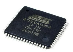
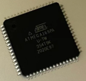
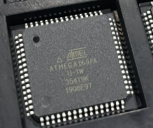
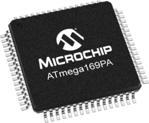
The ATmega169PA microcontroller belongs to the AVR family and is known for combining efficient processing capability with integrated peripheral resources. It provides internal flash program memory, EEPROM storage, and SRAM for dynamic operations. The MCU also includes communication interfaces such as SPI, USART, and TWI, multiple timers, PWM outputs, ADC functionality, and a unique integrated LCD controller that allows the chip to directly drive segmented display panels. Because of these capabilities, the ATmega169PA is commonly deployed in industrial monitoring instruments, smart measurement devices, digital control panels, portable medical equipment, and consumer electronics that require compact display solutions. In these environments, the microcontroller operates as the main processing unit, executing firmware instructions stored within its memory archive while managing sensor input, communication signals, and device logic.
Using the ICRn Register for defining TOP works well when using fixed TOP values. By using ICRn, the OCRnA Register is free to be used for generating a PWM output on OCnA. However, if the base PWM frequency is actively changed (by changing the TOP value), using the OCRnA as TOP is clearly a better choice due to its double buffer feature.
In fast PWM mode, the compare units allow generation of PWM waveforms on the OCnx pins. Setting the COMnx1:0 bits to two will produce a non-inverted PWM and an inverted PWM output can be generated by setting the COMnx1:0 to three (see Table on page 158) if Extract Chip.
The actual OCnx value will only be visible on the port pin if the data direction for the port pin is set as output (DDR_OCnx). The PWM waveform is generated by setting (or clearing) the OCnx Register at the compare match between OCRnx and TCNTn before Extract Chip, and clearing (or setting) the OCnx Register at the timer clock cycle the counter is cleared (changes from TOP to BOTTOM).
The PWM frequency for the output can be calculated by the following equation:
fclk_I/O
fOCnxPWM = ———————————–
The N variable represents the prescaler divider (1, 8, 64, 256, or 1024).
The extreme values for the OCRnx Register represents special cases when generating a PWM waveform output in the fast PWM mode if Extract Chip. If the OCRnx is set equal to BOTTOM (0x0000) the output will be a narrow spike for each TOP+1 timer clock cycle. Setting the OCRnx equal to TOP will result in a constant high or low output (depending on the polarity of the output set by the COMnx1:0 bits.).
A frequency (with 50% duty cycle) waveform output in fast PWM mode can be achieved by setting OCnA to toggle its logical level on each compare match (COMnA1:0 = 1).
This applies only if OCR1A is used to define the TOP value (WGM13:0 = 15). The waveform generated will have a maximum frequency of fOCnA = fclk_I/O/2 when OCRnA is set to zero (0x0000). This feature is similar to the OCnA toggle in CTC mode, except the double buffer feature of the Output Compare unit is enabled in the fast PWM mode.
Extract Chip ATmega169PA Heximal projects often occur when organizations need to hack access to a secured MCU in order to extract, recover, or restore firmware from protected flash and EEPROM memory areas. A locked microcontroller may block external read commands through fuse-level security mechanisms, preventing engineers from copying the binary program file or generating a firmware dump. In more advanced configurations, the chip may include encrypted memory regions or trigger automatic erase operations if unauthorized access attempts are detected. Reverse engineering such a protected microprocessor therefore involves detailed study of the MCU architecture and its memory layout. The objective is to carefully extract a complete binary or heximal archive from the flash program memory and associated EEPROM data while maintaining the integrity of the stored firmware. This process must be performed with precision to avoid corrupting the program file or permanently altering the protected chip.
Successfully recovering firmware from a locked ATmega169PA microcontroller can deliver substantial practical value for technology companies and equipment manufacturers. By restoring the firmware archive and generating a usable binary dump, engineers can reprogram replacement chips, maintain legacy control boards, and support long-term product maintenance. The recovered firmware also allows technical teams to analyze program behavior, reconstruct portions of the source code, and troubleshoot operational issues within complex embedded systems. Instead of abandoning existing hardware or rebuilding software from the ground up, businesses can rely on recovered program data to protect their technological investment and maintain system compatibility. Ultimately, Extract Chip ATmega169PA Heximal services transform a secured microcontroller into a recoverable engineering resource, enabling organizations to extend the lifecycle of their products while preserving the critical firmware stored within protected MCU memory.