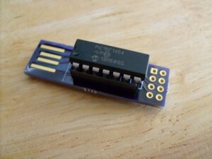
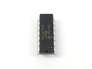
The Microchip MCU PIC16F1454 is a powerful microcontroller that integrates several features, including flash memory and EEPROM, which are essential for storing firmware and program data. However, its secured and protected nature makes it difficult for unauthorized users to access or clone the data contained in its flash memory. The process of extracting or dumping the data from the MCU often requires advanced methods such as reverse engineering or decrypting the binary code.
In some cases, attackers may attempt to crack or hack the MCU to replicate or recover its firmware, potentially enabling them to create counterfeit versions of the chip. Techniques like breaking the security protocols, decoding the encrypted memory, or bypassing locked sections of the microcontroller are used for this purpose. One of the most common methods is to extract the data directly from the flash memory and EEPROM through hardware interfaces, such as SPI or JTAG, to gain access to the source code.
Reverse engineering can also be employed to study the microcontroller’s architecture and identify vulnerabilities in its protection mechanisms. This can lead to the creation of tools that can decrypt the firmware or decode the program to obtain sensitive information. Once the data is acquired, attackers might use it to create a replica of the original chip or microprocessor, ultimately compromising the security of the device.
Moreover, in some legitimate cases, engineers might need to recover data from a corrupted or malfunctioning MCU. The process of dumping the contents of the flash memory and analyzing the archive for errors can help in restoring the integrity of the firmware or program.
For those looking to work with Microchip MCU PIC16F1454, ensuring that your data and firmware are well-protected is crucial, as any vulnerabilities could be exploited for malicious purposes.
We can Copy Microchip MCU PIC16F1454 Flash Memory, please view the Microchip MCU PIC16F1454 features for your reference:
The Timer1 oscillator is also available as a clock source in power-managed modes. By setting the System Clock Select bits, SCS1:SCS0 (OSCCON<1:0>), to ‘01’, the device switches to SEC_RUN mode; both the CPU and peripherals are clocked from the Timer1 oscillator through Extract Microprocessor PIC16C72A Heximal.
If the IDLEN bit (OSCCON<7>) is cleared and a SLEEP instruction is executed, the device enters SEC_IDLE mode. Additional details are available in Section 3.0 “Power-Managed Modes”. Whenever the Timer1 oscillator is providing the clock source when Copy Microprocessor PIC16C74B Firmware, the Timer1 system clock status flag, T1RUN (T1CON<6>), is set. This can be used to determine the controller’s current clocking mode when Copy Microchip MCU PIC16F1454 Flash Memory.

It can also indicate the clock source being currently used by the Fail-Safe Clock Monitor by Crack MCU. If the Clock Monitor is enabled and the Timer1 oscillator fails while providing the clock, polling the T1RUN bit will indicate whether the clock is being provided by the Timer1 oscillator or another source.
The oscillator circuit, shown in below Figure, should be located as close as possible to the microcontroller. There should be no circuits passing within the oscillator circuit boundaries other than VSS or VDD. If a high-speed circuit must be located near the oscillator in order to Read MCU PIC16C73B Eeprom (such as the PWM pin, or the primary oscillator using the OSC2 pin), a grounded guard ring around the oscillator circuit, as shown in Figure 12-4, may be helpful when used on a single-sided PCB, or in addition to a ground plane after Copy Microchip MCU PIC16F1454 Flash Memory.