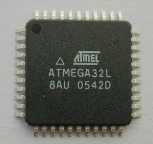
Break AVR Locked ATMEGA32L MCU Flash Memory and restore atmega32l microprocessor memory software in order to clone heximal file to new atmega32l microcontroller chipset;
When the BOOTRST Fuse is unprogrammed, the boot section size set to 2Kbytes and the IVSEL bit in the GICR Register is set before any interrupts are enabled to read atmega32l mcu software from its flash memory, the most typical and general program setup for the Reset and Interrupt Vector Addresses is:
| AddressLabels | Code | Comments | |
| $000
; |
rjmp | RESET | ; Reset handler |
$001 RESET:ldi r16,high(RAMEND); Main program start
$002 out SPH,r16 ; Set Stack Pointer to top of RAM
$003 ldi r16,low(RAMEND)
$004 out SPL,r16
$005 sei ; Enable interrupts
$006 <instr> xxx
;
| .org
$c01 |
$c01 |
rjmp |
EXT_INT0 |
; |
IRQ0 Handler |
| $c02
… $c12 |
rjmp
… rjmp |
EXT_INT1
… ; SPM_RDY |
;
; |
IRQ1 Handler
Store Program Memory Ready Handler
|
When the BOOTRST Fuse is programmed and the boot section size set to 2Kbytes, the most typical and general program setup for the Reset and Interrupt Vector Addresses is:
| AddressLabels | Code | Comments | ||
| .org $001 | ||||
| $001 | rjmp | EXT_INT0 | ; IRQ0 Handler | |
| $002 | rjmp | EXT_INT1 | ; IRQ1 Handler | |
| … | … | … | ; | |
| $012 | rjmp | SPM_RDY | ; Store Program Memory Ready Handler | |
| ; | ||||
| .org $c00
$c00 ; |
rjmp |
RESET |
; Reset handler |
|
| $c01 | RESET:ldi | r16,high(RAMEND); Main program start | ||
| $c02 | out | SPH,r16 ; Set Stack Pointer to top of RAM | ||
| $c03 | ldi | r16,low(RAMEND) | ||
| $c04 | out | SPL,r16 | ||
| $c05 | sei | ; Enable interrupts | ||
$c06 <instr> xxx
When the BOOTRST Fuse is programmed, the boot section size set to 2Kbytes, and the IVSEL bit in the GICR Register is set before any interrupts are enabled, the most typical and general program setup for the Reset and Interrupt Vector Addresses is:
AddressLabels Code Comments
;
.org $c00
$c00 rjmp RESET ; Reset handler
$c01 rjmp EXT_INT0 ; IRQ0 Handler
$c02 rjmp EXT_INT1 ; IRQ1 Handler
… … … ;
$c12 rjmp SPM_RDY ; Store Program Memory Ready Handler
| $c13 | RESET: ldi | r16,high(RAMEND); Main program start |
| $c14 | out | SPH,r16 ; Set Stack Pointer to top of RAM |
| $c15 | ldi | r16,low(RAMEND) |
| $c16 | out | SPL,r16 |
| $c17 | sei | ; Enable interrupts |
$c18 <instr> xxx
When the IVSEL bit is cleared (zero), the Interrupt Vectors are placed at the start of the Flash memory. When this bit is set (one), the Interrupt Vectors are moved to the beginning of the Boot Loader section of the Flash. The actual address of the start of the boot Flash section is deter- mined by the BOOTSZ Fuses. Refer to the section “Boot Loader Support – Read-While-Write Self-Programming” on page 202 for details. To avoid unintentional changes of Interrupt Vector tables, a special write procedure must be followed to change the IVSEL bit:
- Write the Interrupt Vector Change Enable (IVCE) bit to one
- Within four cycles, write the desired value to IVSEL while writing a zero to IVCE
Interrupts will automatically be disabled while this sequence is executed. Interrupts are disabled in the cycle IVCE is set, and they remain disabled until after the instruction following the write to IVSEL. If IVSEL is not written, interrupts remain disabled for four cycles. The I-bit in the Status Register is unaffected by the automatic disabling.