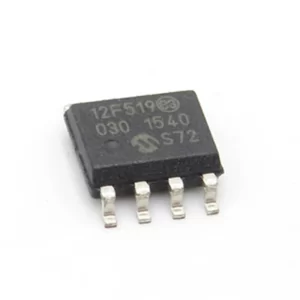
We can Read Microchip MCU PIC12F519 Code, please view the Microchip MCU PIC12F519 features for your reference:
The Analog-to-Digital converter (A/D) allows conversion of an analog input signal to a 10-bit binary representation of that signal. The PIC16F917/916/914/913 has up to eight analog inputs, multiplexed into one sample and hold circuit when read microchip mcu code.
The output of the sample and hold is connected to the input of the converter. The converter generates a binary result via successive approximation and stores the result in a 10-bit register. The voltage reference used in the conversion is software selectable to either VDD or a voltage applied by the VREF pin. Figure 12-1 shows the
block diagram of the A/D on the PIC16F917/916/914/913 if the microchip mcu code being read.
The ANS<7:0> bits (ANSEL<7:0>) and the TRIS bits control the operation of the A/D port pins. Set the corresponding TRIS bits to set the pin output driver to its high-impedance state. Likewise, set the corresponding ANSEL bit to disable the digital input buffer before the mcu code has been read.

There are up to eight analog channels on the PIC16F917/916/914/913, AN<7:0>. The CHS<2:0> bits (ADCON0<4:2>) control which channel is connected to the sample and hold circuit.
There are two options for each reference to the A/D converter, VREF+ and VREF-. VREF+ can be connected to either VDD or an externally applied voltage. Alternatively, VRIF- can be connected to either VSS or an externally applied voltage. VCFG<1:0> bits are used to select the reference source after the microchip mcu code reading.

The A/D conversion cycle requires 11 TAD. The source of the conversion clock is software selectable via the ADCS bits (ADCON1<6:4>). There are seven possible clock options, For correct conversion, the A/D conversion clock (1/TAD) must be selected to ensure a minimum TAD of 1.6 ìs. Table 12-1 shows a few TAD calculations for selected frequencies when microchip mcu code reading.
Shaded cells are outside of recommended range.
The A/D RC source has a typical TAD time of 4s for VDD > 3.0V.
These values violate the minimum required TAD time.
For faster conversion times, the selection of another clock source is recommended.
When the device frequency is greater than 1 MHz, the A/D RC clock source is only recommended if the conversion will be performed during Sleep when readout source code from mcu.

