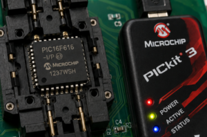
The PIC16F616 from Microchip represents a refined evolution in low-power 8-bit architecture, packing 3.5 Kwords of flash instruction space, 128 bytes of SRAM, and 256 bytes of EEPROM into a compact 14-pin package that quietly governs countless industrial processes. This microcontroller distinguishes itself through dual analog comparators with programmable voltage references, enabling sophisticated threshold detection without external microprocessor support. Its embedded precision internal oscillator eliminates crystal requirements, reducing both bill-of-materials costs and electromagnetic vulnerability in noisy factory environments.
Việc đọc nội dung bộ nhớ flash của vi điều khiển Microchip PIC16F616 bị khóa gặp phải những rào cản đáng kể vì Microchip đã thiết kế kiến trúc bảo vệ của nó để chống lại chính xác loại thao tác trích xuất mà việc bảo tồn yêu cầu. Các công cụ phát triển tiêu chuẩn gặp phải các đường dẫn đọc được mã hóa trả về dữ liệu rác hoặc kích hoạt các cơ chế tự khóa khi có các nỗ lực truy cập trái phép xảy ra. Mảng bộ nhớ của vi điều khiển Microchip PIC16F616 nằm sau các máy trạng thái phần cứng giám sát điện áp, xung nhịp và chuỗi lệnh để phát hiện các bất thường — bất kỳ sự sai lệch nào so với các mẫu dự kiến đều gây ra sự cô lập bộ nhớ chương trình ngay lập tức. Do đó, các dịch vụ phục hồi chuyên nghiệp phải phá vỡ các ranh giới của bộ vi xử lý Microchip PIC16F616 được bảo mật này thông qua các phương pháp không thể bị các mạch phòng thủ của vi điều khiển phát hiện. Quá trình trích xuất firmware tạo ra các luồng thập lục phân thô từ vi điều khiển Microchip PIC16F616, yêu cầu kỹ thuật đảo ngược tiếp theo để tái tạo ý nghĩa chức năng — chuyển đổi các mẫu điện thành các mã nguồn tương đương dễ hiểu, bản đồ tham số EEPROM và tài liệu vận hành mà các nhóm bảo trì thực sự có thể triển khai.
The FSCM is designed to detect an oscillator failure after the Oscillator Start-up Timer (OST) has expired. The OST is used after waking up from Sleep and after any type of Reset. The OST is not used with the EC or RC Clock modes so that the FSCM will be active as soon as the Reset or wake-up has completed.
خواندن محتویات فلش یک میکروکنترلر قفلشدهی Microchip PIC16F616 با موانع بزرگی روبرو است، زیرا Microchip معماری محافظ خود را طوری طراحی کرده است که دقیقاً در برابر نوع عملیات استخراجی که نیاز به نگهداری دارد، مقاومت کند. ابزارهای توسعه استاندارد با مسیرهای خواندن رمزگذاریشدهای مواجه میشوند که دادههای بیارزش را برمیگردانند یا در صورت وقوع تلاشهای دسترسی غیرمجاز، مکانیسمهای خودقفلسازی را فعال میکنند. آرایه حافظه میکروکنترلر Microchip PIC16F616 در پشت ماشینهای وضعیت سختافزاری قرار دارد که ولتاژ، کلاک و توالی دستورالعملها را برای ناهنجاریها رصد میکنند – هرگونه انحراف از الگوهای مورد انتظار باعث جداسازی فوری حافظه برنامه میشود. بنابراین، سرویسهای بازیابی حرفهای باید مرزهای این میکروپردازندهی امن Microchip PIC16F616 را از طریق روشهایی که برای مدارهای دفاعی میکروکنترلر نامرئی هستند، هک کنند. فرآیند تخلیهی میانافزار، جریانهای ششضلعی خام از میکروکنترلر Microchip PIC16F616 را ارائه میدهد که برای بازسازی معنای عملکردی به مهندسی معکوس بعدی نیاز دارند – تبدیل الگوهای الکتریکی به معادلهای کد منبع قابل فهم، نقشههای پارامتر EEPROM و مستندات عملیاتی که تیمهای تعمیر و نگهداری میتوانند در واقع مستقر کنند.
When the FSCM is enabled, the Two-Speed Start-up is also enabled. Therefore, the device will always be executing code while the OST is operating. Due to the wide range of oscillator start-up times, the Fail-Safe circuit is not active during oscillator start-up (i.e., after exiting Reset or Sleep). After an appropriate amount of time, the user should check the OSTS bit of the OSCCON register to verify the oscillator start-up and that the system clock switchover has successfully completed. There are as many as eighteen general purpose I/O pins available. Depending on which peripherals are enabled, some or all of the pins may not be available as general purpose I/O. In general, when a peripheral is enabled, the associated pin may not be used as a general purpose I/O pin.
PORTA is a 6-bit wide, bidirectional port. The corresponding data direction register is TRISA (Register 4-2). Setting a TRISA bit (= 1) will make the corresponding PORTA pin an input (i.e., disable the output driver). Clearing a TRISA bit (= 0) will make the corresponding PORTA pin an output (i.e., enables output driver and puts the contents of the output latch on the selected pin). The exception is RA3, which is input only and its TRIS bit will always read as ‘1’. Example 4-1 shows how to initialize PORTA. Reading the PORTA register (Register 4-1) reads the status of the pins, whereas writing to it will write to the PORT latch. All write operations are read-modify-write operations. Therefore, a write to a port implies that the port pins are read, this value is modified and then written to the PORT data latch. RA3 reads ‘0’ when MCLRE = 1. The TRISA register controls the PORTA pin output drivers, even when they are being used as analog inputs. The user should ensure the bits in the TRISA register are maintained set when using them as analog inputs. I/O pins configured as analog input always read.
लॉक किए गए माइक्रोचिप PIC16F616 MCU के फ्लैश कंटेंट को पढ़ने में बड़ी मुश्किलें आती हैं, क्योंकि माइक्रोचिप ने अपने प्रोटेक्टिव आर्किटेक्चर को ठीक उसी तरह के एक्सट्रैक्ट ऑपरेशन को रोकने के लिए डिज़ाइन किया है, जिसकी प्रिजर्वेशन को ज़रूरत होती है। स्टैंडर्ड डेवलपमेंट टूल्स एन्क्रिप्टेड रीडआउट पाथवे का सामना करते हैं जो अनऑथराइज़्ड एक्सेस की कोशिश होने पर गार्बेज डेटा लौटाते हैं या सेल्फ-लॉकिंग मैकेनिज्म को ट्रिगर करते हैं। माइक्रोचिप PIC16F616 माइक्रोकंट्रोलर का मेमोरी ऐरे हार्डवेयर स्टेट मशीन के पीछे होता है जो वोल्टेज, क्लॉक और इंस्ट्रक्शन सीक्वेंस को एनोमली के लिए मॉनिटर करता है—एक्सपेक्टेड पैटर्न से कोई भी डेविएशन तुरंत प्रोग्राम मेमोरी आइसोलेशन का कारण बनता है। इसलिए प्रोफेशनल रिकवर सर्विसेज़ को इन सिक्योर्ड माइक्रोचिप PIC16F616 माइक्रोप्रोसेसर की बाउंड्रीज़ को उन तरीकों से हैक करना होगा जो माइक्रोकंट्रोलर के डिफेंसिव सर्किट के लिए इनविज़िबल रहते हैं। फर्मवेयर डंप प्रोसेस माइक्रोचिप PIC16F616 माइक्रोकंट्रोलर से रॉ हेक्सिमल स्ट्रीम देता है, जिसके फंक्शनल मीनिंग को रीकंस्ट्रक्ट करने के लिए बाद में रिवर्स इंजीनियरिंग की ज़रूरत होती है—इलेक्ट्रिकल पैटर्न को समझने लायक सोर्स कोड इक्विवेलेंट, EEPROM पैरामीटर मैप और ऑपरेशनल डॉक्यूमेंटेशन में बदलना, जिसे मेंटेनेंस टीम असल में डिप्लॉय कर सकती हैं।
The existential necessity for such flash liberation becomes painfully apparent when legacy infrastructure fails and original design documentation has evaporated. A locked PIC16F616 in a production line controller might contain proprietary PID tuning coefficients, safety interlock sequences, or communication protocol timing that took years of field refinement to perfect. Without the ability to open these encrypted devices and restore their firmware to operational status, organizations face catastrophic choices: attempt black-box reverse engineering of complex electromechanical systems, or abandon entire production lines and absorb millions in revalidation costs. Our extract services eliminate this paralysis by delivering complete archive packages that capture every bit of memory content—both flash instructions and EEPROM calibration tables—enabling faithful program replication on replacement hardware. Clients gain the freedom to manufacture spare controllers, migrate functionality to modern platforms, or simply preserve institutional knowledge against future silicon obsolescence. The recovered binaryfile becomes a permanent engineering asset, immunizing operations against supply chain discontinuity and forgotten data relationships.
Чтение содержимого флэш-памяти заблокированного микроконтроллера Microchip PIC16F616 сопряжено с серьезными трудностями, поскольку Microchip разработала свою защитную архитектуру таким образом, чтобы противостоять именно тем операциям извлечения, которые необходимы для сохранения данных. Стандартные инструменты разработки сталкиваются с зашифрованными путями считывания, которые возвращают некорректные данные или запускают механизмы самоблокировки при попытках несанкционированного доступа. Массив памяти микроконтроллера Microchip PIC16F616 находится за аппаратными конечными автоматами, которые отслеживают напряжение, тактовую частоту и последовательность инструкций на предмет аномалий — любое отклонение от ожидаемых шаблонов приводит к немедленной изоляции памяти программы. Поэтому профессиональным службам восстановления приходится взламывать эти защищенные границы микропроцессора Microchip PIC16F616 с помощью методов, которые остаются невидимыми для защитных схем микроконтроллера. Процесс дампа прошивки дает необработанные шестнадцатеричные потоки данных с микроконтроллера Microchip PIC16F616, которые требуют последующего обратного проектирования для восстановления функционального смысла — преобразования электрических шаблонов в понятные эквиваленты исходного кода, карты параметров EEPROM и операционную документацию, которую группы технического обслуживания могут фактически использовать.
We specialize in transforming locked PIC16F616 devices into fully documented firmware resources through advanced semiconductor analysis capabilities. Our technical approach combines precision physical characterization with proprietary electrical techniques to hack past protected barriers and read complete flash arrays without compromising memory integrity. Every extracted chip undergoes exhaustive verification to ensure dump accuracy before we deliver structured archive outputs—including heximal instruction listings, EEPROMdata maps, and functional source code documentation—that empower your engineering team to restore and reverse engineer legacy systems with confidence. Whether confronting immediate field failures or executing strategic platform migration, we ensure your microcontroller investments remain productive and secured against the irreversible loss of embedded operational intelligence.
تُشكل قراءة محتويات ذاكرة الفلاش لوحدة التحكم الدقيقة Microchip PIC16F616 المُقفلة تحديًا كبيرًا، نظرًا لتصميم Microchip لبنيتها الوقائية خصيصًا لمقاومة عمليات الاستخراج التي تتطلبها عملية الحفظ. تواجه أدوات التطوير القياسية مسارات قراءة مُشفرة تُعيد بيانات غير مفهومة أو تُفعّل آليات القفل الذاتي عند حدوث محاولات وصول غير مُصرح بها. تقع مصفوفة ذاكرة وحدة التحكم الدقيقة Microchip PIC16F616 خلف آلات حالة الأجهزة التي تراقب الجهد والساعة وتسلسلات التعليمات بحثًا عن أي خلل – أي انحراف عن الأنماط المتوقعة يُؤدي إلى عزل فوري لذاكرة البرنامج. لذلك، يتعين على خدمات الاستعادة الاحترافية اختراق حدود معالج Microchip PIC16F616 المُؤمّن من خلال أساليب تبقى غير مرئية لدوائر الحماية الخاصة بوحدة التحكم الدقيقة. تُنتج عملية تفريغ البرامج الثابتة تدفقات سداسية عشرية خام من وحدة التحكم الدقيقة Microchip PIC16F616، والتي تتطلب هندسة عكسية لاحقة لإعادة بناء المعنى الوظيفي – تحويل الأنماط الكهربائية إلى ما يُعادلها من شفرة مصدرية مفهومة، وخرائط معلمات EEPROM، ووثائق تشغيلية يُمكن لفرق الصيانة استخدامها فعليًا.