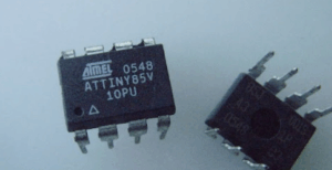
The subject Read Chip ATtiny85V Software refers to the specialized process of accessing and retrieving the internal flash content stored inside an ATtiny85V microcontroller. This device is part of the AVR family and is known for its ultra-low-voltage operation, making it popular in compact battery-powered systems. Inside the chip, engineers store firmware, calibration data, communication protocols, and configuration files, often in binary or heximal format. When the original source code is unavailable, organizations may require techniques to extract, recover, or open the embedded program.
Membaca Perangkat Lunak Microchip ATtiny85V mengacu pada proses khusus untuk mengakses dan mengambil konten flash internal yang tersimpan di dalam mikrokontroler ATtiny85V yang aman. Perangkat ini merupakan bagian dari keluarga AVR dan dikenal karena operasi tegangan ultra-rendahnya, sehingga populer dalam sistem bertenaga baterai yang ringkas. Di dalam chip, para insinyur menyimpan firmware, data kalibrasi, protokol komunikasi, dan berkas konfigurasi, seringkali dalam format biner atau heksimal. Ketika kode sumber asli tidak tersedia, organisasi mungkin memerlukan teknik untuk mengekstrak, memulihkan, atau membuka program tertanam. Salah satu tantangan utama dalam membaca program internal adalah bahwa mikroprosesor terenkripsi Microchip ATtiny85V sering kali memiliki bit perlindungan yang terkunci, aman, atau terenkripsi. Mekanisme ini sengaja dibangun untuk mencegah pembacaan yang tidak sah. Dikombinasikan dengan tata letak yang dienkapsulasi, pad pemrograman yang hilang, atau modul terintegrasi, chip dapat menjadi tidak dapat diakses melalui antarmuka standar. Dalam kasus seperti itu, prosesnya mungkin melibatkan pekerjaan tingkat mikro yang terkontrol dan rekayasa balik yang cermat untuk memastikan arsip asli tetap utuh dan berfungsi. Tujuannya adalah untuk memulihkan informasi tanpa mengubah atau merusak komponen.
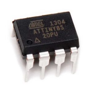
The ATtiny85V is widely deployed in industries such as IoT devices, wearable technology, medical accessories, automotive electronics, smart sensors, decorative LED controllers, and consumer gadgets. Its compact footprint and balanced processing capability allow manufacturers to incorporate intelligence into space-restricted designs. Over time, however, development archives may be lost, documentation may become outdated, or a supplier may stop offering support. When that happens, accessing the internal memory becomes essential to continue maintenance or duplication.
Read Chip ATtiny85V Software from microcontroller ATtiny85V flash memory by unlock MCU ATtiny85V security fuse which can be located when reverse engineering MCU‘s physical structure:
Read Chip ATtiny85V Software from microcontroller ATtiny85V flash memory by unlock MCU ATtiny85V security fuse which can be located when reverse engineering MCU’s physical structure
XTAL1 and XTAL2 are the input and output, respectively, of an inverting amplifier which can be configured for use as an on-chip oscillator, as shown in Figure 1. Either a quartz crystal or ceramic resonator may be used. To drive the device from an external clock source, XTAL2 should be left unconnected while XTAL1 is driven.
There are no requirements on the duty cycle of the external clock signal, since the input to the internal clocking circuitry is through a divide-by-two flip-flop, but minimum and maximum voltage high and low time specifications must be observed if mcu embedded firmware extraction.
माइक्रोचिप ATtiny85V सॉफ्टवेयर को पढ़ने का मतलब है एक सिक्योर्ड ATtiny85V माइक्रोकंट्रोलर के अंदर स्टोर इंटरनल फ्लैश कंटेंट को एक्सेस करने और रिट्रीव करने का खास प्रोसेस। यह डिवाइस AVR फैमिली का हिस्सा है और अपने अल्ट्रा-लो-वोल्टेज ऑपरेशन के लिए जाना जाता है, जिससे यह कॉम्पैक्ट बैटरी से चलने वाले सिस्टम में पॉपुलर है। चिप के अंदर, इंजीनियर फर्मवेयर, कैलिब्रेशन डेटा, कम्युनिकेशन प्रोटोकॉल और कॉन्फ़िगरेशन फाइलें स्टोर करते हैं, जो अक्सर बाइनरी या हेक्सिमल फॉर्मेट में होती हैं। जब ओरिजिनल सोर्स कोड अवेलेबल नहीं होता है, तो ऑर्गनाइजेशन को एम्बेडेड प्रोग्राम को एक्सट्रैक्ट करने, रिकवर करने या खोलने के लिए टेक्नीक की ज़रूरत पड़ सकती है। इंटरनल प्रोग्राम को पढ़ने की मुख्य चुनौतियों में से एक यह है कि एन्क्रिप्टेड माइक्रोप्रोसेसर माइक्रोचिप ATtiny85V में अक्सर लॉक्ड, सिक्योर्ड या एन्क्रिप्टेड प्रोटेक्शन बिट्स होते हैं। ये मैकेनिज्म जानबूझकर बिना इजाज़त के पढ़ने से रोकने के लिए बनाए गए हैं। एनकैप्सुलेटेड लेआउट, मिसिंग प्रोग्रामिंग पैड या इंटीग्रेटेड मॉड्यूल के साथ मिलकर, चिप स्टैंडर्ड इंटरफेस के ज़रिए इनएक्सेसिबल हो सकती है। ऐसे मामलों में, प्रोसेस में कंट्रोल्ड माइक्रो-लेवल वर्क और ओरिजिनल आर्काइव को सही-सलामत और फंक्शनल बनाए रखने के लिए सावधानी से रिवर्स इंजीनियरिंग शामिल हो सकती है। इसका मकसद कम्पोनेंट को बिना बदले या नुकसान पहुंचाए जानकारी को वापस लाना है।
In idle mode, the CPU puts itself to sleep while all the on-chip peripherals remain active. The mode is invoked by software. The content of the on-chip RAM and all the special functions registers remain unchanged.
Figure 2. External Clock Drive Configuration mode. The idle mode can be terminated by any enabled interrupt or by a hardware reset before mcu atmega162 code extraction.
crack microchip secured attiny85v mcu fuse bit and readout flash memory data
It should be noted that when idle is terminated by a hardware reset, the device normally resumes program execution, from where it left off, up to two machine cycles before the internal reset algorithm takes control. On-chip hardware inhibits access to internal RAM in this event, but access to the port pins is not inhibited.
To eliminate the possibility of an unexpected write to a port pin when Idle is terminated by reset, the instruction following the one that invokes Idle should not be one that writes to a port pin or to external memory.
In the power down mode the oscillator is stopped, and the instruction that invokes power down is the last instruction executed. The on-chip RAM and Special Function Registers retain their values until the power down mode is terminated.
The only exit from power down is a hardware reset. Reset redefines the SFRs but does not change the on-chip RAM. The reset should not be activated before VCC is restored to its normal operating level and must be held active long enough to allow the oscillator to restart and stabilize.
Membaca Perisian Microchip ATtiny85V merujuk kepada proses khusus untuk mengakses dan mendapatkan semula kandungan flash dalaman yang disimpan di dalam mikropengawal ATtiny85V yang selamat. Peranti ini merupakan sebahagian daripada keluarga AVR dan dikenali dengan operasi voltan ultra rendahnya, menjadikannya popular dalam sistem berkuasa bateri yang padat. Di dalam cip, jurutera menyimpan firmware, data penentukuran, protokol komunikasi dan fail konfigurasi, selalunya dalam format binari atau heksimal. Apabila kod sumber asal tidak tersedia, organisasi mungkin memerlukan teknik untuk mengekstrak, memulihkan atau membuka program terbenam. Salah satu cabaran utama membaca program dalaman ialah mikropemproses Microchip ATtiny85V yang disulitkan selalunya merangkumi bit perlindungan yang dikunci, selamat atau disulitkan. Mekanisme ini dibina secara sengaja untuk mengelakkan pembacaan yang tidak dibenarkan. Digabungkan dengan susun atur yang dienkapsulasi, pad pengaturcaraan yang hilang atau modul bersepadu, cip boleh menjadi tidak boleh diakses melalui antara muka standard. Dalam kes sedemikian, proses tersebut mungkin melibatkan kerja peringkat mikro yang terkawal dan kejuruteraan terbalik yang teliti untuk memastikan arkib asal kekal utuh dan berfungsi. Matlamatnya adalah untuk memulihkan maklumat tanpa mengubah suai atau merosakkan komponen.
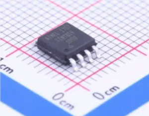
One of the main challenges of reading the internal program is that the ATtiny85V often includes locked, secured, or encrypted protection bits. These mechanisms are intentionally built to prevent unauthorized reading. Combined with encapsulated layouts, missing programming pads, or integrated modules, the chip can become inaccessible through standard interfaces. In such cases, the process may involve controlled micro-level work and careful reverse engineering to ensure the original archive remains intact and functional. The goal is to restore the information without modifying or damaging the component.
Why perform this kind of operation? For many clients, retrieving the software means restoring production capability, extending a product’s life cycle, or verifying functionality against regulatory or manufacturing requirements. It also protects previous engineering investment by preventing the need to rewrite complex logic or re-engineer existing behavior from scratch.
Microchip ATtiny85V 소프트웨어 읽기는 보안된 ATtiny85V 마이크로컨트롤러 내부에 저장된 내부 플래시 콘텐츠에 접근하고 검색하는 특수 프로세스를 의미합니다. 이 장치는 AVR 제품군에 속하며 초저전압 작동으로 유명하여 소형 배터리 구동 시스템에서 널리 사용됩니다. 칩 내부에는 펌웨어, 교정 데이터, 통신 프로토콜 및 구성 파일이 저장되며, 이는 종종 이진 또는 16진수 형식으로 저장됩니다. 원본 소스 코드를 사용할 수 없는 경우, 기업은 내장된 프로그램을 추출, 복구 또는 열기 위한 기술이 필요할 수 있습니다. 내부 프로그램을 읽는 데 있어 주요 과제 중 하나는 암호화된 마이크로프로세서인 Microchip ATtiny85V에 잠금, 보안 또는 암호화된 보호 비트가 포함되어 있다는 것입니다. 이러한 메커니즘은 무단 읽기를 방지하기 위해 의도적으로 설계되었습니다. 캡슐화된 레이아웃, 누락된 프로그래밍 패드 또는 통합 모듈과 결합되면 표준 인터페이스를 통해 칩에 접근할 수 없게 될 수 있습니다. 이러한 경우, 원본 아카이브가 손상되지 않고 작동하도록 하기 위해 제어된 마이크로 레벨 작업과 신중한 역공학이 필요할 수 있습니다. 목표는 구성 요소를 수정하거나 손상시키지 않고 정보를 복원하는 것입니다.
Ultimately, Read Chip ATtiny85V Software is not just about technical access—it is about ensuring continuity, preserving intellectual assets, and giving clients full ownership and control of the technology they rely on.