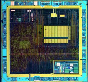
Microchip PIC16LF59 Eeprom Extraction needs to break pic16f59 microcontroller flash fuse bit and then unlock heximal file from pic16f59 MCU flash memory;

The Synchronous Serial Port (SSP) module is a serial interface used to communicate with other peripheral or microcontroller devices. These peripheral devices may be serial EEPROMs, shift registers, display drivers, A/D converters, etc. The SSP module can operate in one of two modes when Read Microprocessor PIC16F677 Heximal:

- Serial Peripheral Interface (SPI)
- Inter-Integrated Circuit (I2C™)Refer to Application Note AN578, “Use of the SSP Module in the Multi-Master Environment” (DS00578). This section contains register definitions and operational characteristics of the SPI module. The SPI mode allows 8 bits of data to be synchronously transmitted and received simultaneously. To accomplish communication, typically three pins are used:
- Serial Data Out (SDO)
- Serial Data In (SDI)
Serial Clock (SCK)Additionally, a fourth pin may be used when in a Slave mode of operation:Note 1: When the SPI is in Slave mode with SS pin control enabled (SSPM<3:0> bits of the SSPCON register = 0100), the SPI module will reset if the SS pin is set to VDD before Read Chip PIC16F616 Flash.
.2: If the SPI is used in Slave mode with CKE = 1, then the SS pin control must be enabled.3: When the SPI is in Slave mode with SS pin control enabled (SSPM<3:0> bits of the SSPCON register = 0100), the state of the SS pin can affect the state read back from the TRISC<4> bit. The peripheral OE signal from the SSP module into PORTC controls the state that is read back from the TRISC<4> bit (see Section 17.0 “Electrical Specifications” for information on PORTC). If read-write-modify instructions, such as BSF, are performed on the TRISC register while the SS pin is high, this will cause the TRISC<7> bit to be set, thus disabling the SDO output.When initializing the SPI, several options need to be specified. This is done by programming the appropriate control bits (SSPCON<5:0> and SSPSTAT<7:6>) when Copy Microcontroller PIC12F635 Firmware.These control bits allow the following to be specified:
Clock Edge (output data on rising/falling edge ofMaster mode (SCK is the clock output)Slave mode (SCK is the clock input), Clock Polarity (Idle state of SCK)Data Input Sample Phase (middle or end of data output time) SCK)
Clock Rate (Master mode only)
Slave Select mode (Slave mode only) before Crack MCU Code

