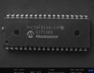
The PIC16F874A microcontroller has earned long-term popularity in embedded system development because of its dependable architecture, integrated EEPROM capability, flexible flash program memory, and strong peripheral support for industrial-grade applications. Designed as part of the widely adopted PIC16 series, this MCU is frequently integrated into factory automation equipment, environmental monitoring systems, laboratory instruments, access control devices, automotive electronics, and intelligent power management products. Its combination of analog-to-digital conversion, serial communication interfaces, timers, and low-power operation makes it especially suitable for durable electronic products requiring stable firmware execution over many years. As older hardware platforms continue operating globally, businesses increasingly search for “Extract Microcontroller PIC16F874A Program” solutions when original firmware archives, source code repositories, or engineering documentation become unavailable after supplier changes, discontinued manufacturing, or accidental data loss.
These devices have a host of features intended to maximize system reliability, minimize cost through elimination of external components, provide power saving operating modes and offer code protection. These are:
- Oscillator Selection
- RESET
– Power-on Reset (POR)
– Power-up Timer (PWRT)
– Oscillator Start-up Timer (OST)
– Brown-out Reset (BOR)
- Interrupts
- Watchdog Timer (WDT)
- SLEEP
- Code Protection
- ID Locations
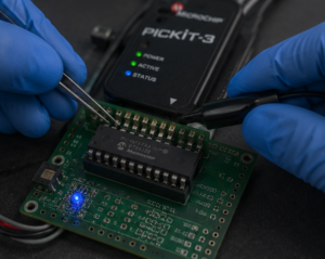
- In-Circuit Serial Programming
These devices have a Watchdog Timer, which can be enabled or disabled, using a configuration bit. It runs off its own RC oscillator for added reliability.
There are two timers that offer necessary delays on power-up. One is the Oscillator Start-up Timer (OST), intended to keep the chip in RESET until the crystal oscillator is stable. The other is the Power-up Timer (PWRT), which provides a fixed delay of 72 ms (nominal) on power-up only. It is designed to keep the part in RESET while the power supply stabilizes, and is enabled or disabled, using a configuration bit. With these two timers on-chip, most applications need no external RESET circuitry. In XT, LP or HS modes, a crystal or ceramic resonator is connected to the OSC1/CLKIN and OSC2/CLKOUT pins to establish oscillation (Figure 12-1).
The PIC16F7X oscillator design requires the use of a parallel cut crystal. Use of a series cut crystal may give a frequency out of the crystal manufacturers specifications. When in HS mode, the device can accept an external clock source to drive the OSC1/CLKIN pin (Figure 12-2). See Figure 15-1 or Figure 15-2 (depending on the part number and VDD range) for valid external clock frequencies. These capacitors were tested with the crystals listed below for basic start-up and operation. These values were not optimized. Different capacitor values may be required to produce acceptable oscillator operation. The user should test the performance of the oscillator over the expected VDD and temperature range for the application.
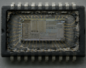
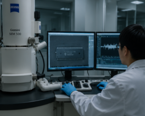
In the field of embedded recovery services, extracting a protected PIC16F874A firmware file involves much more than a standard programming operation. A secured or locked microcontroller may contain encrypted binary data, EEPROM configuration tables, calibration values, production parameters, proprietary flash memory algorithms, and highly valuable source code archives. Reverse engineering specialists attempting to hack, recover, restore, or open protected MCU memory must carefully evaluate multiple technical layers before performing any extraction process. Modern code-protection mechanisms inside the chip are specifically designed to block unauthorized memory access and prevent direct binary dump retrieval from internal flash or EEPROM regions. During a recovery operation, engineers may encounter damaged program sectors, unstable microprocessor behavior, corrupted archive files, degraded silicon structures, or security bits intended to permanently disable external readback functions. Recovering a usable heximal or binary memory archive from a secured PIC16F874A MCU therefore requires extensive analysis of firmware structure, memory mapping, and hardware-level protection responses while maintaining the integrity of the original device.
Unlike ordinary software duplication tasks, reverse engineering a protected PIC16F874A chip often becomes necessary because critical industrial systems continue depending on legacy embedded firmware that no longer has official technical support. Many manufacturers lose access to original source code after mergers, staff turnover, supplier shutdowns, or incomplete project backup procedures. In other situations, companies require firmware extraction to restore obsolete machinery, repair discontinued controller boards, migrate existing program logic into updated hardware, or recover encrypted EEPROM data from failed devices. The technical challenges involved in reading protected flash memory can include locked configuration fuses, secured boot structures, damaged package conditions, incomplete binary archives, and unpredictable memory instability caused by years of operation in harsh industrial environments. These factors make direct access to program files extremely difficult and explain why professional recovery laboratories rely on advanced analysis procedures rather than conventional programming tools alone. The purpose of such recovery services is not unauthorized duplication, but operational continuity, maintenance support, compatibility preservation, and long-term protection of embedded engineering investments.
For clients operating in manufacturing, medical technology, transportation infrastructure, energy control, or commercial automation industries, the successful extraction of PIC16F874A firmware can provide substantial technical and financial advantages. Recovering locked MCU memory enables companies to restore production equipment, duplicate unavailable controller modules, rebuild missing firmware archives, and maintain compatibility with deployed systems already active in the field. Extracted binary files, EEPROM data, and recovered flash program archives may also support diagnostic analysis, hardware modernization, quality verification, and forensic engineering investigations. By preserving secured firmware resources instead of redeveloping entire software platforms from zero, businesses can significantly reduce redevelopment expenses, minimize operational downtime, and shorten maintenance cycles for legacy products. As industrial systems continue relying on long-life microcontroller platforms, professional services focused on extracting PIC16F874A program memory, recovering encrypted firmware files, and restoring protected MCU archives remain increasingly valuable for organizations seeking reliable embedded system continuity and sustainable long-term product support.