Extract MCU PIC16C54 Code focuses on retrieving embedded firmware from a secured, protected, or locked microcontroller where the original development archive has been lost or is no longer accessible. The PIC16C54 belongs to an early generation of OTP-based devices, meaning its program memory is permanently written and cannot be erased or updated. In such conditions, the only remaining copy of the firmware exists inside the chip itself. Through controlled reverse engineering, engineers aim to open restricted access paths, extract a reliable binary dump, and restore the program into a structured heximal file. The goal is to preserve the integrity of the firmware archive while reconstructing a usable representation of the original program stored in the microprocessor.
Операции по извлечению кода из микроконтроллера Microchip PIC16C54 часто требуют от инженеров взлома заблокированного микроконтроллера для извлечения, восстановления и обратного проектирования встроенного ПО из защищенной программной памяти. Поскольку микросхема защищена и разработана таким образом, чтобы предотвратить прямое считывание, процесс извлечения должен тщательно открывать доступ к внутренней памяти, не ставя под угрозу хранящиеся данные. Инженеры работают над получением стабильного бинарного дампа, преобразуют его в связный шестнадцатеричный файл и восстанавливают архив встроенного ПО в пригодный для использования формат. Восстановление встроенного ПО из микроконтроллера Microchip PIC16C54 предоставляет значительные преимущества клиентам, обслуживающим устаревшие системы. Восстанавливая полный бинарный файл или файл программы, организации могут воспроизводить существующие проекты, продлевать жизненный цикл своей продукции и поддерживать непрерывность работы без дорогостоящей переработки. Восстановленный архив встроенного ПО защищенного микропроцессора Microchip PIC16C54 также позволяет проводить более глубокий анализ обратного проектирования, позволяя инженерам интерпретировать системную логику, проверять производительность и восстанавливать недостающий исходный код при необходимости. Такой подход сокращает время простоя, сохраняет интеллектуальную собственность и повышает долгосрочную поддержку системы. В конечном итоге, Extract MCU Microchip PIC16C54 Code превращает защищенный и недоступный чип в ценный инженерный ресурс, обеспечивая устойчивость и гибкость в широком спектре встроенных приложений.
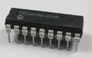
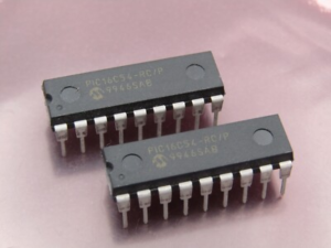
The PIC16C54 microcontroller is designed around a simple yet robust architecture, offering a compact instruction set, predictable execution timing, and essential I/O control. While it lacks EEPROM and modern flash-based flexibility, it remains highly effective for fixed-function embedded applications. Historically, this MCU has been widely deployed in consumer electronics, remote control systems, industrial timers, automotive auxiliary modules, and entry-level automation equipment. In these systems, the firmware stored within the chip functions as a permanent data archive, dictating all operational behavior. Its simplicity and reliability have made it a long-lasting solution in environments where cost efficiency and stability are critical.
Operasi ekstraksi kode MCU Microchip PIC16C54 seringkali mengharuskan para insinyur untuk meretas MCU yang terkunci guna mengekstrak, memulihkan, mengembalikan, dan melakukan rekayasa balik firmware dari memori program yang diamankan. Karena chip tersebut dilindungi dan dirancang untuk mencegah pembacaan langsung, proses ekstraksi harus dengan hati-hati membuka akses ke memori internal tanpa mengganggu data yang tersimpan. Para insinyur berupaya untuk mendapatkan dump biner yang stabil, mengubahnya menjadi file heksadesimal yang koheren, dan membangun kembali arsip firmware ke dalam format yang dapat digunakan. Memulihkan firmware dari MCU Microchip PIC16C54 memberikan keuntungan yang signifikan bagi klien yang memelihara sistem lama. Dengan memulihkan file biner atau program yang lengkap, organisasi dapat mereplikasi desain yang ada, memperpanjang siklus hidup produk mereka, dan mempertahankan kontinuitas operasional tanpa pengembangan ulang yang mahal. Arsip firmware yang dipulihkan dari mikroprosesor Microchip PIC16C54 yang diamankan juga memungkinkan analisis rekayasa balik yang lebih mendalam, memungkinkan para insinyur untuk menafsirkan logika sistem, memvalidasi kinerja, dan membuat ulang kode sumber yang hilang bila diperlukan. Pendekatan ini mengurangi waktu henti, melestarikan kekayaan intelektual, dan meningkatkan dukungan sistem jangka panjang. Pada akhirnya, Extract MCU Microchip PIC16C54 Code mengubah chip yang aman dan tidak dapat diakses menjadi sumber daya teknik yang berharga, memastikan keberlanjutan dan fleksibilitas di berbagai aplikasi tertanam.
Bit 15:12 – Reserved Bits
These bits are reserved for future use. For compatibility with future devices, these bit must be written to zero when UBRRH is written.
Bit 11:0 – UBRR11:0: USART Baud Rate Register
This is a 12-bit register which contains the USART baud rate. The UBRRH contains the four most significant bits, and the UBRRL contains the eight least significant bits of the USART baud rate.
Ongoing transmissions by the Transmitter and Receiver will be corrupted if the baud rate is changed. Writing UBRRL will trigger an immediate update of the baud rate prescaler.
For standard crystal and resonator frequencies, the most commonly used baud rates for asynchronous operation can be generated by using the UBRR settings in Table 106 to Table 109.
MCU माइक्रोचिप PIC16C54 कोड ऑपरेशन को निकालने के लिए अक्सर इंजीनियरों को लॉक किए गए MCU को हैक करना पड़ता है ताकि सुरक्षित प्रोग्राम मेमोरी से फर्मवेयर निकाला जा सके, रिकवर किया जा सके, रिस्टोर किया जा सके और रिवर्स इंजीनियर किया जा सके। क्योंकि चिप सुरक्षित है और डायरेक्ट रीडआउट को रोकने के लिए डिज़ाइन की गई है, इसलिए एक्सट्रैक्शन प्रोसेस को स्टोर किए गए डेटा से समझौता किए बिना इंटरनल मेमोरी तक सावधानी से एक्सेस खोलना चाहिए। इंजीनियर एक स्टेबल बाइनरी डंप पाने, उसे एक कोहेरेंट हेक्सिमल फ़ाइल में बदलने और फर्मवेयर आर्काइव को इस्तेमाल करने लायक फ़ॉर्मेट में फिर से बनाने के लिए काम करते हैं। माइक्रोचिप PIC16C54 MCU से फर्मवेयर रिकवर करने से पुराने सिस्टम को बनाए रखने वाले क्लाइंट को अच्छे फ़ायदे मिलते हैं। एक पूरी बाइनरी या प्रोग्राम फ़ाइल को रिस्टोर करके, ऑर्गनाइज़ेशन मौजूदा डिज़ाइन को कॉपी कर सकते हैं, अपने प्रोडक्ट की लाइफ़साइकल बढ़ा सकते हैं और बिना महंगे रीडेवलपमेंट के ऑपरेशनल कंटिन्यूटी बनाए रख सकते हैं। सुरक्षित माइक्रोप्रोसेसर माइक्रोचिप PIC16C54 का रिकवर किया गया फर्मवेयर आर्काइव ज़्यादा गहरा रिवर्स इंजीनियरिंग एनालिसिस भी मुमकिन बनाता है, जिससे इंजीनियर सिस्टम लॉजिक को समझ सकते हैं, परफ़ॉर्मेंस को वैलिडेट कर सकते हैं और ज़रूरत पड़ने पर गायब सोर्स कोड को फिर से बना सकते हैं। यह तरीका डाउनटाइम कम करता है, इंटेलेक्चुअल प्रॉपर्टी को बचाता है और लंबे समय तक सिस्टम सपोर्ट को बढ़ाता है। आखिर में, Extract MCU माइक्रोचिप PIC16C54 कोड एक सुरक्षित और पहुंच से बाहर चिप को एक कीमती इंजीनियरिंग रिसोर्स में बदल देता है, जिससे कई तरह के एम्बेडेड एप्लिकेशन में सस्टेनेबिलिटी और फ्लेक्सिबिलिटी पक्की होती है।
UBRR values which yield an actual baud rate differing less than 0.5% from the target baud rate, are bold in the table. Higher error ratings are acceptable, but the Receiver will have less noise resistance when the error ratings are high, especially for large serial frames (see “Asynchronous Operational Range” on page 220).
The error values are calculated using the following equation:
BaudRateClosest Match
⎝ BaudRate ⎠
The Universal Synchronous and Asynchronous serial Receiver and Transmitter (USART) can be set to a master SPI compliant mode of operation. The Master SPI Mode (MSPIM) has the following features:
Full Duplex, Three-wire Synchronous Data Transfer
Master Operation
Supports all four SPI Modes of Operation (Mode 0, 1, 2, and 3)
LSB First or MSB First Data Transfer (Configurable Data Order)
마이크로칩 PIC16C54 MCU에서 펌웨어를 추출하는 작업은 종종 엔지니어가 잠겨 있는 MCU에 접근하여 보안 프로그램 메모리에서 펌웨어를 추출, 복구, 복원 및 역설계해야 하는 경우가 있습니다. 이 칩은 직접적인 읽기를 방지하도록 보호되어 있기 때문에 추출 과정에서 저장된 데이터를 손상시키지 않고 내부 메모리에 접근해야 합니다. 엔지니어는 안정적인 바이너리 덤프를 얻고, 이를 일관성 있는 16진수 파일로 변환한 다음, 펌웨어 아카이브를 사용 가능한 형식으로 재구성합니다. 마이크로칩 PIC16C54 MCU에서 펌웨어를 복구하면 레거시 시스템을 유지 관리하는 고객에게 상당한 이점을 제공합니다. 완전한 바이너리 또는 프로그램 파일을 복원함으로써 기업은 기존 설계를 복제하고, 제품 수명 주기를 연장하며, 비용이 많이 드는 재개발 없이 운영 연속성을 유지할 수 있습니다. 또한, 보안 마이크로프로세서인 마이크로칩 PIC16C54에서 복구된 펌웨어 아카이브를 통해 심층적인 역설계 분석이 가능해지므로 엔지니어는 시스템 로직을 해석하고, 성능을 검증하고, 필요한 경우 누락된 소스 코드를 재구성할 수 있습니다. 이러한 접근 방식은 가동 중지 시간을 줄이고, 지적 재산을 보호하며, 장기적인 시스템 지원을 강화합니다. 궁극적으로 Microchip PIC16C54 MCU 코드 추출은 보안이 강화되어 접근이 불가능했던 칩을 귀중한 엔지니어링 자원으로 탈바꿈시켜 광범위한 임베디드 애플리케이션 전반에 걸쳐 지속 가능성과 유연성을 보장합니다.
Việc trích xuất mã nguồn vi điều khiển Microchip PIC16C54 thường yêu cầu các kỹ sư phải xâm nhập vào vi điều khiển bị khóa để trích xuất, khôi phục, phục hồi và phân tích ngược firmware từ bộ nhớ chương trình được bảo mật. Vì chip được bảo vệ và thiết kế để ngăn chặn việc đọc trực tiếp, quá trình trích xuất phải mở quyền truy cập vào bộ nhớ trong một cách cẩn thận mà không làm ảnh hưởng đến dữ liệu được lưu trữ. Các kỹ sư phải làm việc để có được một bản sao nhị phân ổn định, chuyển đổi nó thành một tệp thập lục phân mạch lạc và xây dựng lại kho lưu trữ firmware thành định dạng có thể sử dụng được. Khôi phục firmware từ vi điều khiển Microchip PIC16C54 mang lại những lợi ích đáng kể cho khách hàng đang duy trì các hệ thống cũ. Bằng cách khôi phục một tệp nhị phân hoặc tệp chương trình hoàn chỉnh, các tổ chức có thể sao chép các thiết kế hiện có, kéo dài vòng đời sản phẩm của họ và duy trì tính liên tục hoạt động mà không cần phải phát triển lại tốn kém. Kho lưu trữ firmware được khôi phục của bộ vi xử lý được bảo mật Microchip PIC16C54 cũng cho phép phân tích kỹ thuật ngược sâu hơn, cho phép các kỹ sư diễn giải logic hệ thống, xác thực hiệu suất và tạo lại mã nguồn bị thiếu khi cần thiết. Cách tiếp cận này giảm thời gian ngừng hoạt động, bảo vệ tài sản trí tuệ và tăng cường hỗ trợ hệ thống lâu dài. Tóm lại, việc trích xuất mã MCU Microchip PIC16C54 biến một con chip được bảo mật và không thể truy cập thành một nguồn tài nguyên kỹ thuật có giá trị, đảm bảo tính bền vững và linh hoạt trên nhiều ứng dụng nhúng khác nhau.