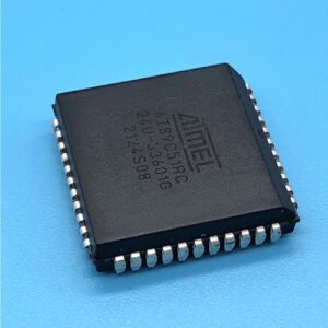
The AT89C51RC is a popular 8051-based microcontroller with built-in Flash memory (32KB) and EEPROM (2KB). Extracting code from this microcontroller can be necessary for reverse engineering, firmware recovery, or debugging. However, many devices have read protection enabled, making extraction challenging. This article discusses methods to extract code from the Flash and EEPROM of a protected AT89C51RC.
The AT89C51RC has a security lock feature that prevents unauthorized reading of the Flash and EEPROM contents. If the lock bits are set, standard programmers cannot read the memory. Common protection levels include:
-
Level 1: No code verification but prevents further programming.
-
Level 2: Disables external memory execution and verification.
-
Level 3: Locks the chip completely, blocking Flash and EEPROM reads.
Extracting code from a protected microcontroller may violate intellectual property laws. Ensure you have legal permission before attempting any extraction. Extracting code from a secured AT89C51RC requires technical expertise and specialized tools. While software-based attacks may work on weakly protected chips, heavily secured devices may need invasive methods like decapping. Always follow ethical guidelines and legal regulations when reverse-engineering embedded systems.
Extract IC AT89C51RC Code from the flash and eeprom memory, the first step is to locate the security fuse bit of the microcontroller AT89C51RC and then disable it by MCU Cracking technique.
Timer 2 is a 16-bit Timer/Counter that can operate as either a timer or an event counter. The type of operation is selected by bit C/T2 in the SFR T2CON (shown in Table 5-2). Timer 2 has three operating modes: capture, auto-reload (up or down counting), and baud rate generator.
The modes are selected by bits in T2CON, as shown in Table 13-1. Timer 2 consists of two 8-bit registers, TH2 and TL2. In the Timer function, the TL2 register is incremented every machine cycle. Since a machine cycle consists of 12 oscillator periods, the count rate is 1/12 of the oscillator frequency.
In the Counter function, the register is incremented in response to a 1-to-0 transition at its corre- sponding external input pin, T2. In this function, the external input is sampled during S5P2 of every machine cycle. When the samples show a high in one cycle and a low in the next cycle, the count is incremented after Extract microcontroller embedded firmware.
The new count value appears in the register during S3P1 of the cycle following the one in which the transition was detected. Since two machine cycles (24 oscillator periods) are required to recognize a 1-to-0 transition, the maximum count rate is 1/24 of the oscillator frequency. To ensure that a given level is sampled at least once before it changes, the level should be held for at least one full machine cycle.
In the capture mode, two options are selected by bit EXEN2 in T2CON. If EXEN2 = 0, Timer 2 is a 16-bit timer or counter which upon overflow sets bit TF2 in T2CON. This bit can then be used to generate an interrupt. If EXEN2 = 1, Timer 2 performs the same operation, but a 1-to-0 transition at external input T2EX also causes the current value in TH2 and TL2 to be captured into RCAP2H and RCAP2L, respectively. In addition, the transition at T2EX causes bit EXF2 in T2CON to be set.
The EXF2 bit, like TF2, can generate an interrupt. The capture mode is illustrated in Figure 13-1. Timer 2 can be programmed to count up or down when configured in its 16-bit auto-reload mode. This feature is invoked by the DCEN (Down Counter Enable) bit located in the SFR T2MOD (see Table 13-2). Upon reset, the DCEN bit is set to 0 so that timer 2 will default to count up. When DCEN is set, Timer 2 can count up or down, depending on the value of the T2EX pin.
Figure 13-2 shows Timer 2 automatically counting up when DCEN=0. In this mode, two options are selected by bit EXEN2 in T2CON. If EXEN2 = 0, Timer 2 counts up to 0FFFFH and then sets the TF2 bit upon overflow. The overflow also causes the timer registers to be reloaded with the 16-bit value in RCAP2H and RCAP2L. The values in Timer in Capture Mode RCAP2H and RCAP2L are preset by software
If EXEN2 = 1, a 16-bit reload can be triggered either by an overflow or by a 1-to-0 transition at external input T2EX. This transition also sets the EXF2 bit. Both the TF2 and EXF2 bits can generate an interrupt if enabled. Setting the DCEN bit enables Timer 2 to count up or down, as shown in Figure 13-2. In this mode, the T2EX pin controls the direction of the count. A logic 1 at T2EX makes Timer 2 count The timer will overflow at 0FFFFH and set the TF2 bit. This overflow also causes the 16-bit value in RCAP2H and RCAP2L to be reloaded into the timer registers, TH2 and TL2, respectively.
A logic 0 at T2EX makes Timer 2 count down. The timer underflows when TH2 and TL2 equal the values stored in RCAP2H and RCAP2L. The underflow sets the TF2 bit and causes 0FFFFH to be reloaded into the timer registers. The EXF2 bit toggles whenever Timer 2 overflows or underflows and can be used as a 17th bit of resolution. In this operating mode, EXF2 does not flag an interrupt.