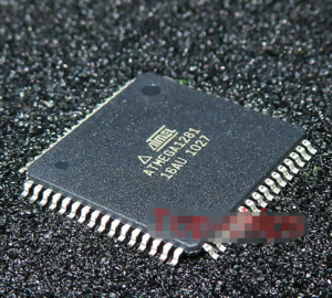
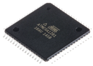
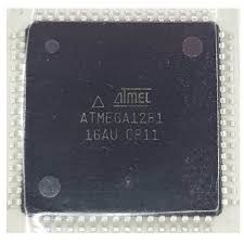
Copying a microcontroller ATmega1281 program from flash and EEPROM memory refers to a specialized engineering process aimed at obtaining a reliable binary or heximal representation of the internal firmware stored in a secured device. The ATmega1281 is a high-performance AVR MCU featuring a large on-chip flash program space, non-volatile EEPROM, and flexible peripheral integration, making it widely adopted in complex embedded systems.
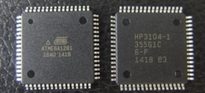
From a technical standpoint, the ATmega1281 integrates an 8-bit RISC microprocessor core, up to 128 KB of flash memory, multiple UARTs, SPI and I²C interfaces, as well as advanced timers. These features support sophisticated program execution and stable data handling. As a result, this chip is frequently deployed in industrial controllers, communication gateways, power management equipment, transportation electronics, and customized automation products. In such applications, the embedded firmware, configuration data, and calibration values are often protected, locked, or partially encrypted to prevent unauthorized access.
Features
- High Performance, Low Power AVR® 8-Bit Microcontroller
- Advanced RISC Architecture
– 135 Powerful Instructions – Most Single Clock Cycle Execution
– 32 x 8 General Purpose Working Registers
– Fully Static Operation
– Up to 16 MIPS Throughput at 16 MHz
– On-Chip 2-cycle Multiplier
Non-volatile Program and Data Memories
– 64K/128K/256K Bytes of In-System Self-Programmable Flash
Endurance: 10,000 Write/Erase Cycles
– Optional Boot Code Section with Independent Lock Bits
In-System Programming by On-chip Boot Program
True Read-While-Write Operation
– 4K Bytes EEPROM
Endurance: 100,000 Write/Erase Cycles
– 8K Bytes Internal SRAM after Copy Microcontroller
– Up to 64K Bytes Optional External Memory Space
– Programming Lock for Software Security
JTAG (IEEE std. 1149.1 compliant) Interface
– Boundary-scan Capabilities According to the JTAG Standard
– Extensive On-chip Debug Support when read at89c51id2 Microcontroller
– Programming of Flash, EEPROM, Fuses, and Lock Bits through the JTAG Interface
However, real-world business scenarios frequently require controlled access to this internal memory. When original source code is unavailable, documentation is missing, or a legacy product must be maintained, companies may need to extract or recover the program image directly from the MCU. In these cases, copying the flash and EEPROM contents into a structured dump or archive becomes the only viable option to restore functionality or enable system upgrades.
The primary difficulty in this process lies in overcoming security mechanisms without damaging the device. Standard readout interfaces are intentionally blocked, and any improper open attempt may erase critical memory regions. A reckless hack approach can permanently destroy valuable firmware and operational data. Therefore, professional reverse engineering focuses on stability, repeatability, and data integrity rather than speed. The objective is to retrieve a consistent file containing executable code, configuration memory, and supporting data that can be validated and reused.
Peripheral Features
– Two 8-bit Timer/Counters with Separate Prescaler and Compare Mode
– Four 16-bit Timer/Counter with Separate Prescaler, Compare- and Capture Mode
– Real Time Counter with Separate Oscillator
– Four 8-bit PWM Channels
– Six/Twelve PWM Channels with Programmable Resolution from 2 to 16 Bits (ATmega1281/2561, ATmega640/1280/2560)
– Output Compare Modulator
– 8/16-channel, 10-bit ADC
– Two/Four Programmable Serial USART (ATmega1281/2561,ATmega640/1280/2560)
– Master/Slave SPI Serial Interface
– Byte Oriented 2-wire Serial Interface
– Programmable Watchdog Timer with Separate On-chip Oscillator
– On-chip Analog Comparator
– Interrupt and Wake-up on Pin Change
Special Microcontroller Features
– Power-on Reset and Programmable Brown-out Detection
– Internal Calibrated Oscillator
– External and Internal Interrupt Sources
– Six Sleep Modes: Idle, ADC Noise Reduction, Power-save, Power-down, Standby, and Extended Standby
I/O and Packages
– 51/86 Programmable I/O Lines (ATmega1281/2561, ATmega640/1280/2560)
– 64-lead (ATmega1281/2561)
– 100-lead (ATmega640/1280/2560)
– 100-lead TQFP (64-lead TQFP Option)
Temperature Range:
– -40°C to 85°C Industrial
Speed Grade:
Programmable Flash
– ATmega1281/2561V/ATmega640/1280/2560V: 0 – 4 MHz @ 1.8 – 5.5V, 0 – 8 MHz @ 2.7 – 5.5V
– ATmega640/1280/1281/2560/2561: 0 – 8 MHz @ 2.7 – 5.5V, 0 – 16 MHz @ 4.5 – 5.5V before Copy Microcontroller